
Contents | 1. Introduction to structural design | 2. Loads | 3. Wood | 4. Steel |
Introduction to reinforced concrete | Material properties | Sectional properties | Design approaches | Construction systems | Tension elements |
Concrete columns are cast into forms containing a matrix of steel reinforcement. This reinforcement is distributed just inside the perimeter of the forms in a pattern designed to confine the concrete, much like sand would be confined when placed into a steel drum. In both cases (sand in a steel drum; concrete in a steel "cage"), the ability of the material to sustain an axial compressive stress is enormously increased by the presence of the confining steel, whether or not the steel contributes directly to the support of the external load.
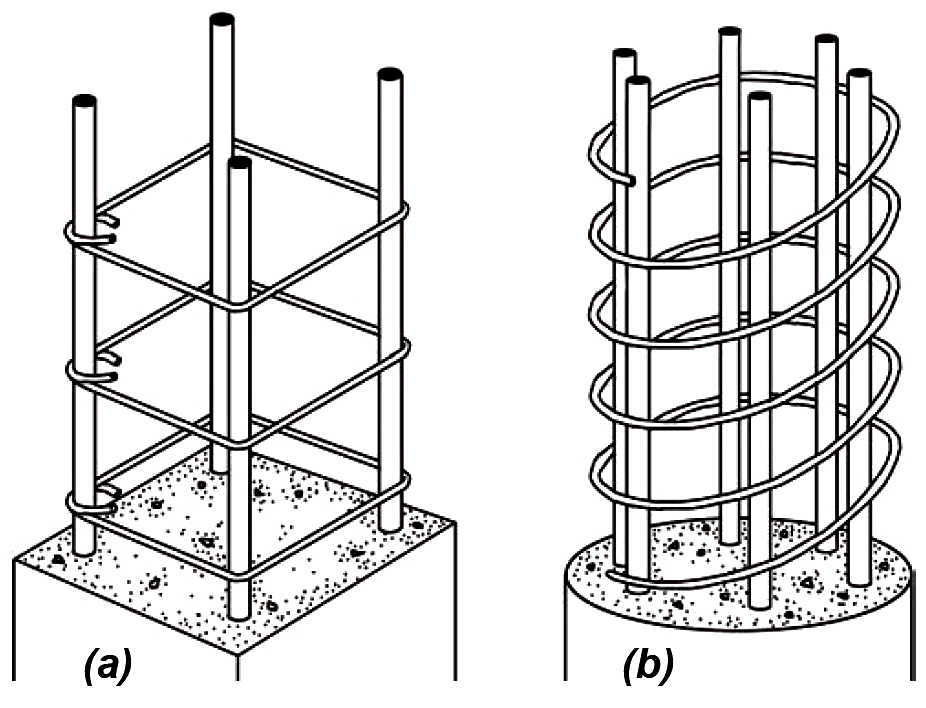
Two patterns of steel reinforcement are commonly used for columns: a series of square or rectangular ties (Figure 5.16a) placed horizontally around a minimum of four longitudinal steel bars; or a continuous circular spiral wire (Figure 5.16b) wrapped around a minimum of six longitudinal bars. Tied columns are usually rectangular and spiral columns are usually circular, but either pattern of reinforcement can be used for any column cross section. In general, spiral reinforcement provides more reliable confinement of the concrete, and a more ductile type of failure than tied columns; strength reduction factors for spiral versus tied columns take this relative safety into account. The actual design of ties and spirals is based on fairly straight-forward guidelines, summarized in Appendix Table A-5.4. The design and analysis examples that follow do not include the calculation of tie or spiral spacing and size.
The amount of longitudinal steel in reinforced concrete columns, measured according to the ratio of steel area to gross column area (reinforcement ratio), must fall between two limiting values. The lower limit of 1% provides a minimum amount of steel to protect against tension failures due to unanticipated bending moments; the upper limit of 8% prevents overcrowding of steel bars within the concrete formwork. Because longitudinal column reinforcement is typically spliced — and therefore doubled in area — where an upper column is cast above a lower column (see Figure 5.53), it is common to limit the maximum reinforcement ratio to 4%. The reinforcement ratio is defined as:
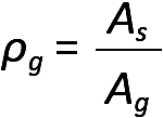
where ρg = the reinforcement ratio of longitudinal steel area to gross area; As = the cross-sectional area of longitudinal reinforcement; and Ag = the gross cross-sectional area of the concrete column, whether the column is rectangular or circular in section. It is also possible that for columns of a given cross-sectional area with relatively small loads, even the minimum steel area (1% of the gross column area) might be greater than required to resist the load. In such cases, it is permitted to compute the required and minimum steel area on the basis of the portion of the concrete area that is required, rather than the entire concrete area actually provided — as long as this "required" area is no less than one half of the actual area. In other words, for such columns with relatively small loads, the reinforcement ratio, computed on the basis of the actual area, can be as low as 0.5%, but only when the applied loads can be resisted using only half the concrete area.
It is assumed in this chapter that reinforced concrete column stability is not a factor in the column's strength; that is, the column is not slender enough for buckling to be a problem. As a general rule of thumb, concrete columns braced against lateral misalignment ("sidesway"), with a slenderness ratio, KL/r, no greater than 40, are rarely influenced by stability considerations. Taking the radius of gyration of a rectangular column as approximately equal to 0.3 times the smaller cross-sectional column dimension, h (that is, assuming r = 0.3h), and taking the effective length coefficient, K = 1.0, we get KL/r = 1.0L/ (0.3h) ≤ 40. Solving for the ratio of unbraced length, L, to minimum cross-sectional dimension, h, we find that slenderness effects may typically be neglected in axially-loaded reinforced concrete columns when L/h ≤ 12. For slender concrete columns, other techniques must be used to account for the possibility of buckling.
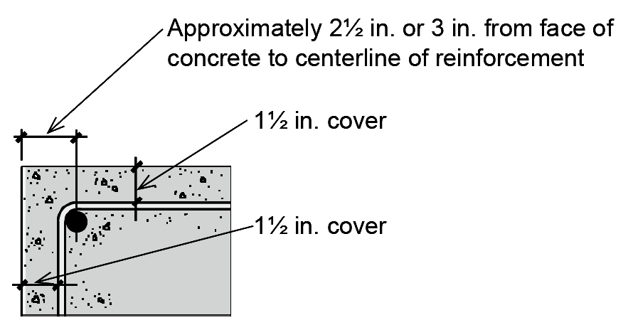
For columns, at least 1½ in. of concrete is left outside the matrix of reinforcement to protect it from corrosion and to provide fire resistance (2 in. for No. 6 or larger bars if the concrete is exposed to the weather, or the earth; 3 in. for all bars if the concrete is cast directly against the earth — see Appendix Table A-5.1). For typical reinforcement sizes, the distance from the outside of the concrete column to the centerline of the longitudinal reinforcement can be taken as about 2½ in. or 3 in. (Figure 5.17).
For a reinforced concrete column subjected to pure axial compression, the ultimate load at failure is simply the concrete strength (failure stress) times its area, plus the yield stress of the longitudinal steel rebars times their area (Figure 5.18).
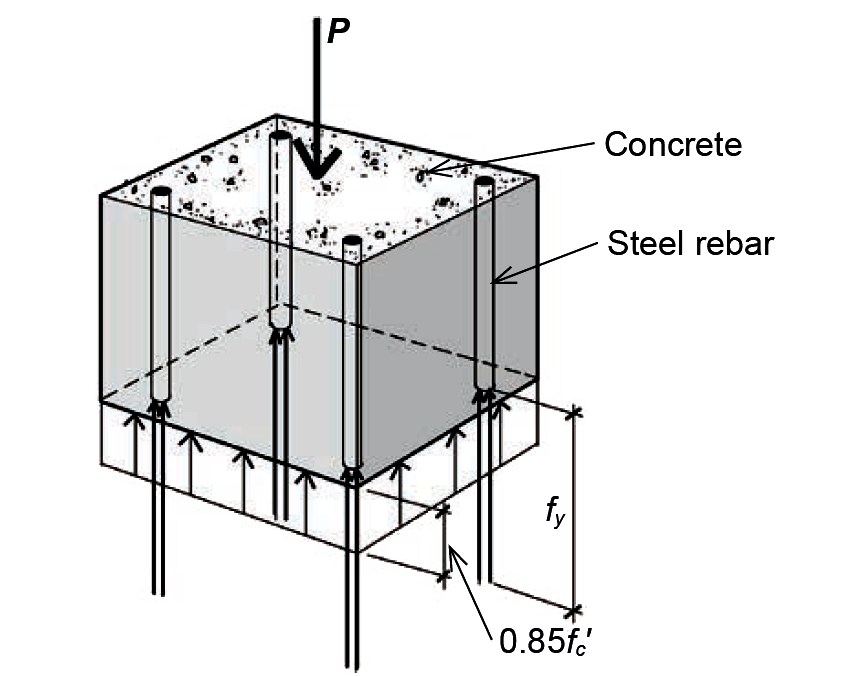
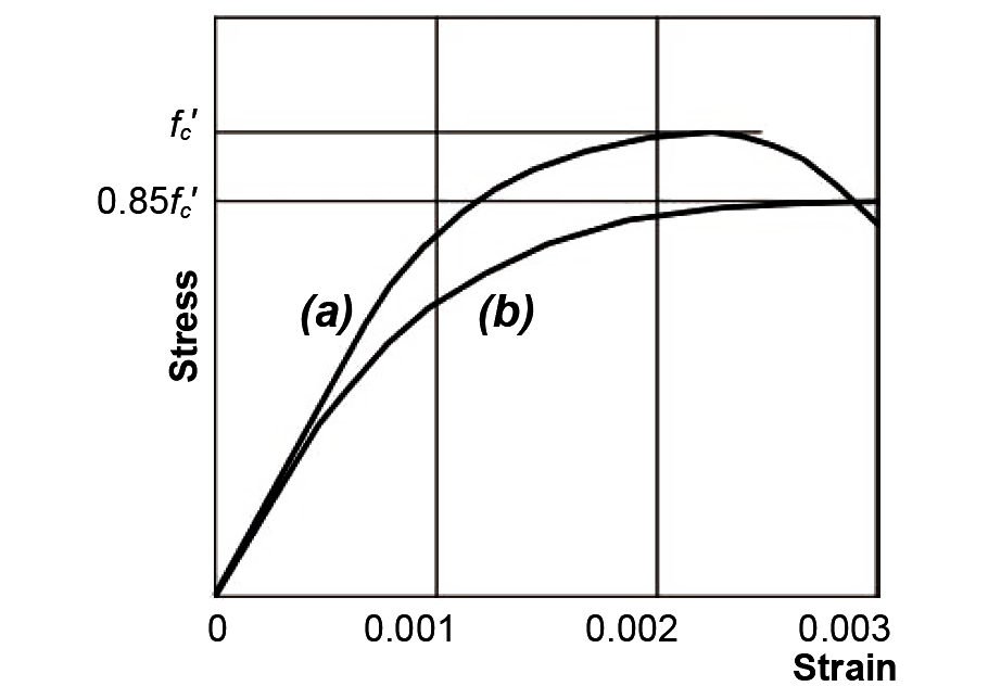
The failure strength of concrete is taken as 85% of its cylinder strength, fc', since the more rapid rate of loading of the test cylinders (Figure 5.19, curve a), compared to loading of actual structural columns (Figure 5.19, curve b), results in a higher measured strength than can be expected for real structures.
The strain at which steel longitudinal reinforcement bars yield depends on their yield stress. For grade 60 rebars (fy = 60 ksi), the yield strain (stress divided by modulus of elasticity) is 60/29,000 = 0.002. For grade 40 ( fy = 40 ksi), the yield strain is 40/29,000 = 0.001. In either case, the failure stress of the steel can be taken as its yield stress, fy , since yielding would have already occurred when the concrete reaches its crushing strain (precipitating column failure) of about 0.003. Combining the failure stresses for concrete and steel, we get an ultimate failure load for an axially- loaded column of:
where As is the longitudinal steel area, and Ac is the net area of concrete, that is, the gross cross-sectional area minus the steel area.
There are two strength reduction safety factors for axially-loaded reinforced concrete columns: φ is the ordinary factor, while α accounts for the possibility of non-axial loading. Both factors depend on whether the column is tied or spiral (see Appendix Table A-5.5). Combining these strength reduction factors with factored loads (typically 1.2D + 1.6L where live and dead load govern, per Appendix Table A-2.7a), we get equations for the design and analysis of axially-loaded reinforced concrete columns. An example of such an equation for dead load (D) and live load (L) only, where Pu is the factored or "design" load, is:
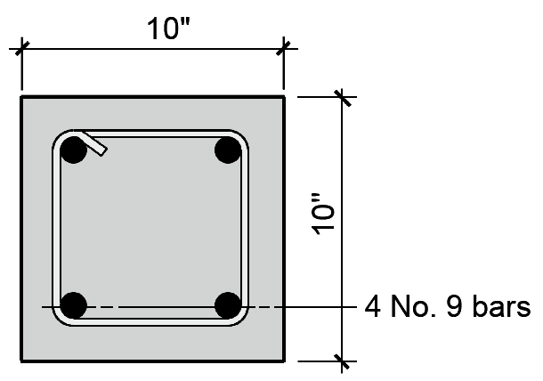
Problem definition. Assuming fc' = 4 ksi and fy = 60 ksi, find the nominal failure capacity of a 10 in. × 10 in. axially-loaded tied rectangular column with 4 No. 9 bars, as shown in Figure 5.20. Can this column support a live load of 100 kips and a dead load of 100 kips?
Solution overview. Find concrete and steel areas; multiply by failure stresses for concrete and steel and add together for ultimate capacity. Multiply ultimate capacity by strength reduction factors and compare with factored loads to determine whether capacity is adequate for given loads.
Problem solution
1. From Appendix Table A-5.2, the steel area for 4 No. 9 bars, As = 4.00 in2.
2. The concrete area, Ac = Ag – As = 10 × 10 – 4.00 = 96 in2.
3. From Equation 5.2, the nominal capacity or failure load, Pn = 0.85fc'Ac + fyAs = 0.85(4)(96) + 60(4.00) = 566.4 kips.
4. From Appendix Table A-5.2, strength reduction factors for a tied column are: φ = 0.65 and α = 0.80.
5. Based on Equation 5.3, check whether Pu = 1.2D + 1.6L ≤ φα(Pn). We get: Pu = 1.2D + 1.6L = 1.2(100) + 1.6(100) = 280 kips; and φα(Pn) = (0.65)(0.80)(566.4) = 294.5 kips. Therefore, since Pu ≤ φα(Pn), the capacity is adequate and the column is OK.
6. In this example, all column parameters were given. However, we can still check that the column has an acceptable reinforcement ratio and that the bars fit within the cross section. Using Equation 5.1, we check that the reinforcement ratio is between 1% and 8% (that is, between 0.01 and 0.08): ρg = As /Ag = 4.00/100 = 0.040, so the reinforcement ratio is OK. Using Appendix Table A-5.3, we find that, for 2 No.9 bars in one line, we need 7.94 in. Since we actually have 10 in., the bars fit.
Problem definition. Assuming fc' = 3 ksi and fy = 60 ksi, find the required steel area for an axially-loaded 12-in.-square tied reinforced concrete column supporting a dead load (D) of 150 kips and a live load (L) of 100 kips. Select bar size.
Solution overview. Use Equation 5.3 relating reduced strength to factored loads and solve for steel area. The area of concrete within the column cross section is found by subtracting the steel area from the gross cross-sectional dimensions; that is, Ac = Ag – As. Check reinforcement ratio limits and bar fit.
Problem solution
1. From Equation 5.3: Pu = 1.2D + 1.6L ≤ φα(0.85fc' Ac + fyAs). Finding strength reduction factors, φ and α, from Appendix Table A-5.5, we get:
1.2(150) + 1.6(100) ≤ (.65)(.80)[0.85(3)(144 – As) + 60As].
340 ≤ (0.52)[367.2 – 2.55As + 60As].
653.85 ≤ 367.2 + 57.45As.
57.45As ≥ 286.65.
As ≥ 4.99 in2. This is the required steel area for longitudinal bars.2. From Appendix Table A-5.2, choose 4 No. 10 bars with actual As = 5.08 in2. For symmetry, the number of bars is limited to 4, 6, 8, and so on.
3. Using Equation 5.1, check that the reinforcement ratio is between 1% and 8% (that is, between 0.01 and 0.08): ρg = As/Ag = 5.08/144 = 0.035, so the reinforcement ratio is OK. Using Appendix Table A-5.3, we find that for two No. 10 bars in one line, we need 8.38 in. Since we actually have 12 in., the bars fit.
Problem definition. Assuming fc' = 5 ksi and fy = 60 ksi, select a diameter and find the required steel area for an axially-loaded spirally-reinforced circular reinforced concrete column supporting a dead load (D) of 150 kips and a live load (L) of 125 kips. Select bar size. Check reinforcement ratio and bar fit.
Solution overview. Use Equation 5.3 relating reduced strength to factored loads and solve for gross area. With the reinforcement ratio, ρg, assumed, the area of concrete within the column cross section, Ac = (1.00 – ρg)Ag and the steel area, As = ρg Ag. Find the required gross area, select column dimensions (in this case, the column diameter), and proceed as in Example 5.2 with gross area known. Check reinforcement ratio limits and bar fit.
Problem solution
1. From Equation 5.3: Pu = 1.2D + 1.6L ≤ φα(0.85fc'Ac + fyAs). Since Ac = (1.00 – ρg)Ag and the steel area, As = ρg Ag, we get:
Pu = 1.2D + 1.6L ≤ φα[0.85fc' (1.00 – ρg)Ag + fy ρg Ag]
The choice of a reinforcement ratio is somewhat arbitrary; we select ρg = 0.04; then, with strength reduction factors, φ and α, found from Appendix Table A-5.5, we get:
1.2(150) + 1.6(125) ≤ (.75)(.85)[0.85(5)(1.00 – 0.04)Ag + 60(0.04)Ag].
380 ≤ (0.6375)[4.08Ag + 2.40Ag].
596.1 ≤ 6.48Ag.
Ag ≥ 91.99 in2; since Ag = πr2, the required radius for the concrete column, r =  =
5.41 in. Therefore, the required diameter, d = 2r = 2(5.41) = 10.8 in. The actual diameter that we select may be either bigger or smaller than this "required" diameter, since it was computed on the basis of a desired reinforcement ratio, which need not be — and cannot be — matched precisely in practice (since the actual bar area selected typically exceeds the required area, and since the actual diameter of the column is rounded to the nearest inch or "even" inch. We therefore select a column diameter close to the required value, say 10 in., and proceed as in Example 5.2, with the gross column area given.
=
5.41 in. Therefore, the required diameter, d = 2r = 2(5.41) = 10.8 in. The actual diameter that we select may be either bigger or smaller than this "required" diameter, since it was computed on the basis of a desired reinforcement ratio, which need not be — and cannot be — matched precisely in practice (since the actual bar area selected typically exceeds the required area, and since the actual diameter of the column is rounded to the nearest inch or "even" inch. We therefore select a column diameter close to the required value, say 10 in., and proceed as in Example 5.2, with the gross column area given.
2. From Equation 5.3: Pu = 1.2D + 1.6L ≤ φα(0.85fc' Ac + fyAs). The strength reduction factors, φ and α, from Appendix Table A-5.5, have already been found, the gross area of a circular column with a 10 in. diameter is πr2 = π 52 = 78.54 in2, and we get:
1.2(150) + 1.6(125) ≤ (.75)(.85)[0.85(5)(78.54 – As) + 60As].
380 ≤ (0.6375)[333.8 – 4.25Ass + 60As].
596.1 ≤ 333.8 + 55.75As.
55.75As ≥ 262.3.
As ≥ 4.71 in2. This is the required steel area for longitudinal bars.
3. From Appendix Table A-5.2, choose 6 No. 8 bars with actual As = 4.74 in2. For spiral columns, the number of bars must be at least 6.
4. Using Equation 5.1, check that the reinforcement ratio is between 1% and 8% (that is, between 0.01 and 0.08): ρg = As /Ag = 4.74/78.54 = 0.060, so the reinforcement ratio is OK. Using Appendix Table A-5.3, we find that for 6 No.8 bars in the column, we need a 10.00 in. diameter. Since we actually have a 10 in. diameter, the bars fit.
The actual reinforcement ratio, ρg = 0.060, is much higher than our initial assumed value of ρg = 0.04. Had we selected a 12 in. diameter column instead of a 10 in. diameter column at the end of step 1, the actual steel ratio would have been much lower than 0.04. In other words, the practical requirement to use whole even numbers for column diameter, together with the need to select bar areas corresponding to actual rebar sizes, often makes it difficult to precisely define the reinforcement ratio in advance. This method does, however, lead to a reasonable size for the column in cases where a range of reasonable sizes is not initially known.
© 2020 Jonathan Ochshorn; all rights reserved. This section first posted November 15, 2020; last updated May 28, 2024.