
Contents | 1. Introduction to structural design |
Introduction to loads | Dead loads | Live loads | Environmental loads | Design approaches |
Table A-2.1: Dead loads
| A. Basic volumetric weights in pounds per cubic foot (pcf) | Stone: Sandstone Granite Marble |
144 165 173 |
|---|---|
| Brick/CMU/concrete Normal-weight reinforced concrete |
100 – 145 150 |
| Metals: Aluminum Steel Lead |
165 492 710 |
| Glass | 160 |
| Wood | 25 – 50 |
| Water | 64 |
| Earth: Dry clay Silt, moist and packed Wet sand and gravel |
63 96 120 |
| Insulation: Glass fiber batts Expanded polystyrene boards Extruded polystyrene boaards Polyisocyanurate boards Fiberboard |
0.8 0.9 – 1.8 2.2 2.0 1.5 |
| B. Distributed loads in pounds per square feet (psf) | |
|---|---|
| Wood floor system: 2 × 10 joists at 16 in. on center, wood finish floor and subfloor, gypsum board ceiling | 10.5 |
| Steel floor system: 4-1/2 in. corrugated steel deck with concrete slab, tile floor, mechanical ducts, suspended tile ceiling | 47 |
| Concrete floor system: 6 in. reinforced concrete slab, tile floor, mechanical ducts, suspended tile ceiling | 80 |
| Floor-ceiling components: Harwood finish floor, 7/8 in. Wood subfloor, 3/4 in. Acoustical tile with suspended steel channels Mechanical duct allowance Steel stud partition allowance |
4.0 2.5 3.0 4.0 8.0 |
| Sheathing: Plywood, per 1/8 in. thickness Gypsum board, per 1/8 in. thickness |
0.40 0.55 |
Table A-2.2: Live loads
| A. Typical live loads based on occupancy (psf) | |
|---|---|
| Assembly areas with fixed seats | 60 |
| Assembly areas with movable seats | 100 |
| Lobbies, corridors (first floor) | 100 |
| Dining rooms and restaurants | 100 |
| Garages for passenger cars | 40 |
| Libraries, reading rooms | 60 |
| Libraries, stack areas (not less than) | 150 |
| Manufacturing, light | 125 |
| Manufacturing, heavy | 250 |
| Office buildings | 50 |
| Dwellings and hotels (except as noted below) | 40 |
| Note: Residential sleeping areas | 30 |
| Schools (classrooms) | 40 |
| Schools (corridors above first floor) | 80 |
| Stadium and arena bleachers | 100 |
| Stairs and exitways | 100 |
| Stores, retail (first floor) | 100 |
| Stores, retail (upper floors) | 75 |
| Stores, wholesale (all floors) | 125 |
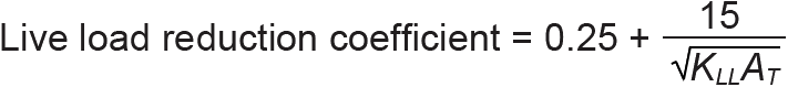
| B.Live load reduction coefficient1,2,3,4 |
|---|
 |
Notes for Part B:
1. KLL is the live load element factor and is defined as follows for selected common beam and column configurations:
KLL = 4 for columns without cantilever slabs
KLL = 3 for edge columns with cantilever slabs
KLL = 2 for corner columns with cantilever slabs
KLL = 2 for beams (except as noted below)
KLL = 1 for one-way and two-way slabs, edge beams with cantilever slabs, and anything else not previously mentioned — and note that AT for one-way slabs cannot be taken as more than 1.5 × (slab span)2
2. AT is the tributary area of the element being considered (ft2)
3. No live load reduction applies when KLLAT ≤ 400 ft2 or when the element supports a single floor with live load > 100 psf (for an element supporting more than one floor with live loads > 100 psf, a reduction no greater than 20% is permitted)
4. Reduction coefficient cannot be taken greater than 1.0; nor can it be smaller than 0.5 for elements supporting a single floor level; or smaller than 0.4 for all other conditions.
Table A-2.3: Environmental loads1
| City, State | Ground Snow Load (psf) | Basic (Ultimate) Wind Speed, V (mph) | Seismic Ground Motion2 | |||||
|---|---|---|---|---|---|---|---|---|
| Risk Category I | Risk Category II | Risk Category III | Risk Category IV | Ss | S1 | TL | ||
| Boston, MA | 40 | 110 | 120 | 128 | 133 | 0.270 | 0.065 | 6 |
| Chicago, IL | 25 | 100 | 107 | 114 | 119 | 0.116 | 0.063 | 12 |
| Little Rock, AR | 10 | 98 | 105 | 111 | 115 | 0.387 | 0.150 | 12 |
| Houston, TX | 0 | 128 | 136 | 145 | 150 | 0.068 | 0.039 | 12 |
| Ithaca, NY | 40 | 100 | 110 | 116 | 122 | 0.119 | 0.045 | 6 |
| Miami, FL | 0 | 157 | 169 | 182 | 189 | 0.040 | 0.020 | 8 |
| New York, NY | 20 | 106 | 115 | 125 | 129 | 0.288 | 0.060 | 6 |
| Philadelphia, PA | 25 | 105 | 112 | 123 | 125 | 0.180 | 0.047 | 6 |
| Phoenix, AZ | 0 | 95 | 101 | 108 | 112 | 0.179 | 0.065 | 6 |
| Portland, ME | 50 | 103 | 112 | 119 | 125 | 0.281 | 0.072 | 6 |
| San Francisco, CA | 0 | 86 | 91 | 98 | 102 | 1.500 | 0.600 | 12 |
Notes:
1. Approximate values taken from snow, wind, and seismic maps. Various web-based applications are available to find environmental loads at specific locations in the U.S. See, for example:
SNOW, WIND, and SEISMIC: https://hazards.atcouncil.org/ [Applied Technology Council (ATC)]
SEISMIC (disaggregated): https://seismicmaps.org/ [California's Office of Statewide Health Planning and Development (OSHPD)]
2. Ss and S1 are, respectively, the maximum considered earthquake ground motions of 0.2s (short) and 1s (long) spectral response acceleration (5% of critical damping) for site class B, measured as a fraction of the acceleration due to gravity. TL is the so-called "long-period transition period" (seconds).
Table A-2.4: Snow load Importance factor, Is
| Category | Description | Factor |
|---|---|---|
| I | Low hazard (minor storage, etc.) | 0.8 |
| II | Regular (ordinary buildings) | 1.0 |
| III | Substantial hazard (schools, jails, places of assembly with no fewer than 300 occupants) | 1.1 |
| IV | Essential facilities (hospitals, fire stations, etc.) | 1.2 |
Table A-2.5: Wind coefficients
| A. Velocity pressure coefficient, Kz1 | |||
|---|---|---|---|
| Height above grade2, z (ft) | Exposure B3 | Exposure C4 | Exposure D5 |
| 500 | 1.57 | 1.78 | 1.90 |
| 400 | 1.47 | 1.69 | 1.82 |
| 300 | 1.35 | 1.59 | 1.73 |
| 200 | 1.20 | 1.46 | 1.62 |
| 100 | 0.99 | 1.27 | 1.43 |
| 90 | 0.96 | 1.24 | 1.41 |
| 80 | 0.93 | 1.21 | 1.38 |
| 70 | 0.89 | 1.17 | 1.35 |
| 60 | 0.85 | 1.14 | 1.31 |
| 50 | 0.81 | 1.09 | 1.27 |
| 45 | 0.79 | 1.07 | 1.25 |
| 40 | 0.76 | 1.04 | 1.22 |
| 35 | 0.73 | 1.01 | 1.19 |
| 30 | 0.70 | 0.98 | 1.16 |
| 25 | 0.67 | 0.95 | 1.13 |
| 20 | 0.62 | 0.90 | 1.08 |
| 0 – 15 | 0.57 | 0.85 | 1.03 |
Notes for Part A:
1. Values of Kz are based on the following equation, where z is the height above grade (ft); α = 7.0 for Exposure B; 9.5 for Exposure C, and 11.5 for Exposure D; and zg = 1200 for Exposure B; 900 for Exposure C; and 700 for Exposure D:
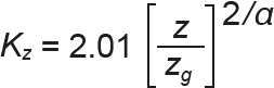
When using tabular values for K, linear interpolation between values is permitted.
2. When computing pressures on windward surfaces, use height z corresponding to height for which pressure is being computed; for all other surfaces, use z = h (mean roof height: i.e., use this single value of z for the entire surface). See Table A-2.5 Part H for graphic explanation of building geometry parameters.
3. Exposure B refers to urban or suburban areas, wooded areas, etc.
4. Exposure C refers to open terrain with scattered obstructions, excluding water surfaces in hurricane regions.
5. Exposure D refers to flat, unobstructed areas like mud flats, salt flats, or water, both inside or outside of hurricane regions.
| B. External pressure coefficient for walls, Cp1 | |||
|---|---|---|---|
| Orientation | 0 ≤ L/B ≤ 1 | L/B = 2 | L/B ≥ 4 |
| Windward | 0.8 | 0.8 | 0.8 |
| Leeward | –0.5 | –0.3 | –0.2 |
| Side | –0.7 | –0.7 | –0.7 |
Note for Part B:
1. L and B are the plan dimensions of the rectangular building, with B being the dimension of the windward and leeward walls, and L the dimension of the side walls. See Table A-2.5 Part H for graphic explanation of building geometry parameters.
| C. External pressure coefficient on windward slope of roof, Cp, for wind direction normal to ridge1,2,7 | |||
|---|---|---|---|
| Roof angle, θ (deg) | h/ L ≤ 0.25 | h/ L = 0.50 | h/ L ≥ 1.0 |
| 6θ < 10 0 < D ≤ h/2 h/ 2 < D ≤ h h < D ≤ 2h 2h < D |
–0.9, -0.18 –0.9, -0.18 –0.5, -0.18 –0.3, -0.18 |
–0.9, -0.18 –0.9, -0.18 –0.5, -0.18 –0.3, -0.18 |
3–1.3, -0.18 –0.7, -0.18 –0.7, -0.18 –0.7, -0.18 |
| 6θ = 10 | –0.7, –0.18 | –0.9, –0.18 | 3–1.3, –0.18 |
| θ = 15 | –0.5, 40.0 | –0.7, –0.18 | –1.0, –0.18 |
| θ = 20 | –0.3, 0.2 | –0.4, 40.0 | –0.7, –0.18 |
| θ = 25 | –0.2, 0.3 | –0.3, 0.2 | –0.5, 40.0 |
| θ = 30 | –0.2, 0.3 | –0.2, 0.2 | –0.3, 0.2 |
| θ = 35 | 40.0, 0.4 | –0.2, 0.3 | –0.2, 0.2 |
| θ = 45 | 0.4 | 40.0, 0.4 | 40.0, 0.3 |
| 5θ ≥ 60 | 0.01θ | 0.01θ | 0.01θ |
Notes for Part C:
1. Where two values are given, either may apply, and both must be considered. Interpolation between adjacent values is permitted, but must be between numbers of the same sign; where no number of the same sign exists, use 0.0.
2. Values are used with Kz taken at mean roof height. Units of length for D, h, and L must be consistent with each other. For roof angles less than 10°, D refers to the range of horizontal distances from the windward eave (edge) for which the value of Cp applies; h is the height of the eave above grade for roof angles no greater than 10°, otherwise, h is the mean roof height above grade; L is the horizontal length of the building parallel to the wind direction. See Table A-2.5 Part H for graphic explanation of building geometry parameters.
3. Value of –1.3 may be reduced depending on the area it is acting on: for areas no greater than 100 ft2, no reduction; for areas of 200 ft2, multiply by 0.9; for areas no smaller than 1000 ft2, multiply by 0.8; interpolate between given values.
4. Values of 0.0 are used only to interpolate between adjacent fields.
5. Roof angles over 80° are treated as windward walls, with Cp = 0.8.
6. See Note 2 for roof height, h, where roof angle is no greater than 10°.
7. Negative numbers indicate "suction," i.e., forces acting away from the building surface; positive numbers indicate forces "pushing" against the building surface.
Table A-2.5: Wind coefficients (continued)
| D. External pressure coefficient on leeward slope of roof, Cp, for wind direction normal to ridge1,2,3 | |||
|---|---|---|---|
| Roof angle, θ (deg) | h/L ≤ 0.25 | h/L = 0.50 | h/L ≥ 1.0 |
| θ = 10 | –0.3 | –0.5 | –0.7 |
| θ = 15 | –0.5 | –0.5 | –0.6 |
| θ ≥ 20 | –0.6 | –0.6 | –0.6 |
Notes for Part D:
1. The height h is measured to the eave for roof angles equal to 10°, otherwise, h is the mean roof height above grade; L is the horizontal length of the building parallel to the wind direction. See Table A-2.5 Part H for graphic explanation of building geometry parameters.
2. For roof angles less than 10°, the roof is considered to be flat, and no leeward pressures are computed. Instead, use the values in Table A.2.4 Part C for the entire roof.
3. Interpolation is permitted between values.
4. Negative numbers indicate "suction," i.e., forces acting away from the building surface; positive numbers indicate forces "pushing" against the building surface.
| E. External pressure coefficient roof, Cp, for wind direction parallel to ridge, for all roof angles1,2,4,5 | |||
|---|---|---|---|
| Applicable Roof Area | h/L ≤ 0.25 | h/L = 0.50 | h/L ≥ 1.0 |
| 0 < D ≤ h/2 | –0.9, –0.18 | -0.9, –0.18 | 3–1.3, –0.18 |
| h/ 2 < D ≤ h | –0.9, –0.18 | -0.9, –0.18 | –0.7, –0.18 |
| h < D ≤ 2h | –0.5, –0.18 | –0.5, –0.18 | –0.7, –0.18 |
| 2h < D | –0.3, –0.18 | –0.3, –0.18 | –0.7, –0.18 |
Notes for Part E:
1. Where two values are given, either may apply, and both must be considered. Interpolation between adjacent values is permitted, but must be between numbers of the same sign.
2. Values are used with K taken at mean roof height. Units of length for D, h, and L must be consistent with each other. For all roof angles, D refers to the range of horizontal distances from the windward eave (edge) for which the value of Cp applies; h is the height of the eave above grade for roof angles no greater than 10°, otherwise, h is the mean roof height above grade; L is the horizontal length of the building parallel to the wind direction. See Table A-2.5 Part H for graphic explanation of building geometry parameters.
3. Value of –1.3 may be reduced depending on the area it is acting on: for areas no greater than 100 ft2, no reduction; for areas of 200 ft2, multiply by 0.9; for areas no smaller than 1000 ft2, multiply by 0.8; interpolate between given values.
4. Roof angles over 80° are treated as windward walls, with Cp = 0.8.
5. Negative numbers indicate "suction," i.e., forces acting away from the building surface; positive numbers indicate forces "pushing" against the building surface.
| F. Gust effect factor, G |
|---|
| In lieu of more complex calculations, use G = 0.85 for so-called "rigid" buildings: such buildings are in most cases no more than 4 times taller than their minimum width, and have a fundamental frequency of at least 1 Hz (1 cycle per second). |
| G. Importance factor, Iw | ||
|---|---|---|
| Category | Description | Factor1 |
| I | Low hazard (minor storage, etc.) | — |
| II | Regular (ordinary buildings) | — |
| III | Substantial risk to human life or major economic impact, with or without significant disruption of daily life | — | IV | Essential facilities (hospitals, fire stations, etc.) | — |
Note for Part G:
1. Importance factors for wind are no longer used directly in calculations; instead, consideration of importance (risk) has been incorporated within basic wind speed maps and wind speed values.
| H. Graphic definition of building parameters1 | 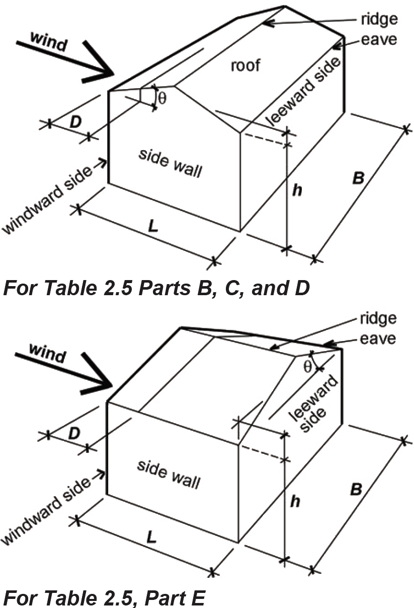 |
|---|
Note for Part H:
1. When using Table A-2.5 Parts C, D, and E, the roof height, h, is measured to the mean roof elevation, except for roof angles less than or equal to 10°, in which case h is measured to the eave, as indicated by the dotted line.
Table A-2.5: Wind coefficients (continued)
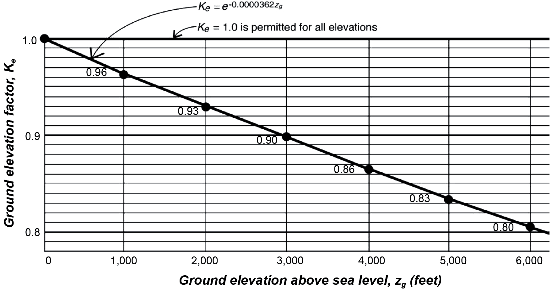
| I. Ground elevation factor |
|---|
 |
Notes for Part I:
1. The ground elevation factor is permitted to be taken, conservatively, as 1.0 for all buildings at or above sea level; or, nonconservatively, as 1.0 for buildings below sea level.
2. Alternatively, values for buildings at ground level elevations between 0 and 6,000 feet can be interpolated from the values shown in the graph above.
3. The values in the graph are based on the equation, Ke = e–0.0000362Kg; this equation — with Kg being the ground elevation above sea level in feet — can be used in lieu of the values shown above and, in fact, for any elevation, whether below sea level or greater than 6,000 feet above sea level. In this equation, e is the base of the natural logarithms ("Euler's number") and is approximately equal to 2.718. In many common spreadsheet programs — with the elevation above sea level (feet) in cell A1 — the equation for Ke would be written as: =EXP(-0.0000362 * A1).
Table A-2.6: Seismic coefficients
| A. Site coefficient, Fa | ||||||
|---|---|---|---|---|---|---|
| Ss ≤ 0.25 | Ss = 0.5 | Ss = 0.75 | Ss = 1.0 | Ss = 1.25 | Ss ≥ 1.5 | |
| A = hard rock | 0.8 | 0.8 | 0.8 | 0.8 | 0.8 | 0.8 |
| B = rock | 0.9 | 0.9 | 0.9 | 0.9 | 0.9 | 0.9 |
| C = dense soil or soft rock | 1.3 | 1.3 | 1.2 | 1.2 | 1.2 | 1.2 |
| D = stiff soil | 1.6 | 1.4 | 1.2 | 1.1 | 1.0 | 1.0 |
| E = soft soil | 2.4 | 1.7 | 1.3 | Need site-specific investigation | ||
| F = liquifiable soils, etc. | Need site-specific investigation | |||||
| B. Site coefficient, Fv | ||||||
|---|---|---|---|---|---|---|
| S1 ≤ 0.1 | S1 = 0.2 | S1 = 0.3 | S1 = 0.4 | S1 = 0.5 | S1 ≥ 0.6 | |
| A = hard rock | 0.8 | 0.8 | 0.8 | 0.8 | 0.8 | 0.8 |
| B = rock | 0.8 | 0.8 | 0.8 | 0.8 | 0.8 | 0.8 |
| C = dense soil or soft rock | 1.5 | 1.5 | 1.5 | 1.5 | 1.5 | 1.4 |
| D = stiff soil | 2.4 | 12.2 | 12.0 | 11.9 | 11.8 | 11.7 |
| E = soft soil | 4.2 | Need site-specific investigation | ||||
| F = liquifiable soils, etc. | Need site-specific investigation | |||||
Note for Part B:
1. Site-specific investigation may be required in certain cases where S1 ≥ 0.2 in Site Class D.
| C. Design elastic response acceleration, SDS and SD1 | |
|---|---|
| 1,2SDS = (2/3)(Fa)(Ss) | 1SD1 = (2/3)(Fa)(S1) |
Note for Part C:
1. See Table A-2.3 for selected values of Ss and S1. See Table A-2.5, Parts A and B for Fa and Fv respectively.
2. In certain circumstances, the value of SDS used in the calculation of Cs and Ev can be taken as the larger of 1.0 and 0.7SDS. In particular, the structure must be no higher than five stories, must have no irregularities, must be Risk Category I or II and Site Class A through D. There are additional requirements involving a so-called redundancy factor, ρ, that would need to be checked for Site Class D; this examination is beyond the scope of this book.
Table A-2.6: Seismic coefficients (continued)
| D. Response modification coefficient, R (including height and other limitations based on seismic design category1) | |
|---|---|
| 01. Special reinforced concrete shear walls (1,2categories D, E limited to 160 ft; F limited to 100 ft) | 5 |
| 02. Ordinary reinforced concrete shear walls (1not permitted in categories D – F) | 4 |
| 03. Detailed plain concrete shear walls (1not permitted in categories C – F) | 2 |
| 04. Ordinary plain concrete shear walls (1not permitted in categories C – F) | 1.5 |
| 05. Intermediate precast shear walls (1,2categories D – F limited to 40 ft) | 4 |
| 06. Ordinary precast shear walls (1not permitted in categories C – F) | 3 |
| 07. Special reinforced masonry shear walls (1categories D, E limited to 160 ft; F limited to 100 ft) | 5 |
| 08. Intermediate reinforced masonry shear walls (1not permitted in categories D – F) | 3.5 |
| 09. Ordinary reinforced masonry shear walls (1not permitted in categories D – F; C limited to 160 ft) | 2 |
| 10. Detailed plain masonry shear walls (1not permitted in categories C – F) | 2 |
| 11. Ordinary plain masonry shear walls (1not permitted in categories C – F) | 1.5 |
| 12. Prestressed masonry shear walls (1not permitted in categories C – F) | 1.5 |
| 13. Ordinary reinforced AAC [Autoclaved Aerated Concrete] masonry shear walls (1category C limited to 35 ft; not permitted in categories D – F) | 2 |
| 14. Ordinary plain AAC [Autoclaved Aerated Concrete] masonry shear walls (1not permitted in categories C – F) | 1.5 |
| 15. Light-frame (wood) walls sheathed with wood structural panels rated for shear resistance, or steel sheets (1categories D – F limited to 65 ft) | 6.5 |
| 16. Light-frame (cold-formed steel) walls sheathed with wood structural panels rated for shear resistance, or steel sheets (1categories D – F limited to 65 ft) | 6.5 |
| 17. Light-frame walls with shear panels of all other materials (1category D limited to 35 ft; not permitted in categories E, F) | 2 |
| 18. Light-frame (cold-formed steel) wall systems using flat strap bracing (1categories D – F limited to 65 ft) | 4 |
| 01. Steel eccentrically braced frames (1,2categories D, E limited to 160 ft; F limited to 100 ft) | 8 |
| 02. Steel special concentrically braced frames (1,2categories D, E limited to 160 ft; F limited to 100 ft) | 6 |
| 03. Steel ordinary concentrically braced frames (1categories D, E limited to 35 ft; category F not permitted) | 3.25 |
| 04. Special reinforced concrete shear walls (1,2categories D, EE limited to 160 ft; F limited to 100 ft) | 6 |
| D. Response modification coefficient, R (including height and other limitations based on seismic design category1) | |
|---|---|
| 05. Ordinary reinforced concrete shear walls (1not permitted in categories D – F) | 5 |
| 06. Detailed plain concrete shear walls (1not permitted in categories C – F) | 2 |
| 07. Ordinary plain concrete shear walls (1not permitted in categories C – F) | 1.5 |
| 08. Intermediate precast shear walls (1,2categories D – F limited to 40 ft) | 5 |
| 09. Ordinary precast shear walls (1not permitted in categories C – F) | 4 |
| 10. Composite steel and concrete eccentrically braced frames (1categories D, E limited to 160 ft; F limited to 100 ft) | 8 |
| 11. Steel and concrete composite special concentrically braced frames (1categories D, E limited to 160 ft; F limited to 100 ft) | 5 |
| 12. Ordinary composite steel and concrete braced frames (1not permitted in categories D – F) | 3 |
| 13. Steel and concrete composite plate shear walls (1categories D, E limited to 160 ft; F limited to 100 ft) | 6.5 |
| 14. Steel and concrete composite special shear walls (1categories D, E limited to 160 ft; F limited to 100 ft) | 6 |
| 15. Steel and concrete composite ordinary shear walls (1not permitted in categories D – F) | 5 |
| 16. Special reinforced masonry shear walls (1categories D, E limited to 160 ft; F limited to 100 ft) | 5.5 |
| 17. Intermediate reinforced masonry shear walls (1not permitted in categories D – F) | 4 |
| 18. Ordinary reinforced masonry shear walls (1category C limited to 160 ft; not permitted in categories D – F) | 2 |
| 19. Detailed plain masonry shear walls (1not permitted in categories C – F) | 2 |
| 20. Ordinary plain masonry shear walls (1not permitted in categories C – F) | 1.5 |
| 21. Prestressed masonry shear walls (1not permitted in categories C – F) | 1.5 |
| 22. Light-frame (wood) walls sheathed with wood structural panels rated for shear resistance (1categories D – F limited to 65 ft) | 7 |
| 23. Light-frame (cold-formed steel) walls sheathed with wood structural panels rated for shear resistance, or steel sheets (1categories D – F limited to 65 ft) | 7 |
| 24. Light framed walls with shear panels — all other materials (1not permitted in categories E – F; D limited to 35 ft) | 2.5 |
| 25. Buckling-restrained braced frames (1,2categories D, E limited to 160 ft; F limited to 100 ft) | 8 |
| 26. Steel special plate shear walls (1,2categories D, E limited to 160 ft; F limited to 100 ft) | 7 |
Table A-2.6: Seismic coefficients (continued)
| D. Response modification coefficient, R (including height and other limitations based on seismic design category1) | |
|---|---|
| 01. Special steel moment frames (no limits) | 8 |
| 02. Special steel truss moment frames (1category D limited to 160 ft; E limited to 100 ft; not permitted in category F) | 7 |
| 03. Intermediate steel moment frames (1,2category D limited to 35 ft; not permitted in categories E – F) | 4.5 |
| 04. Ordinary steel moment frames (1,2not permitted in categories D – F) | 3.5 |
| 05. Special reinforced concrete moment frames (no limits) | 8 |
| 06. Intermediate reinforced concrete moment frames (1not permitted in categories D – F) | 5 |
| 07. Ordinary reinforced concrete moment frames (1not permitted in categories C – F) | 3 |
| 08. Special composite steel and concrete moment frames (no limits) | 8 |
| 09. Steel and concrete composite intermediate moment frames (1not permitted in categories D – F) | 5 |
| 10. Steel and concrete composite partially restrained moment frames (1categories B, C limited to 160 ft; D limited to 100 ft; not permitted in categories E, F) | 6 |
| 11. Steel and concrete composite ordinary moment frames (1not permitted in categories C – F) | 3 |
| 12. Cold-formed steel — special bolted moment frame (1limited to 35 ft in all categories) | 3.5 |
| 01. Steel eccentrically braced frames (no limits) | 8 |
| 02. Special steel concentrically braced frames (no limits) | 7 |
| 03. Special reinforced concrete shear walls (no limits) | 7 |
| 04. Ordinary reinforced concrete shear walls (1not permitted in categories D – F) | 6 |
| 05. Composite steel and concrete eccentrically braced frames (no limits) | 8 |
| 06. Composite steel and concrete special concentrically braced frames (no limits) | 6 |
| 07. Steel and concrete composite plate shear walls (no limits) | 7.5 |
| 08. Steel and concrete composite special shear walls with steel elements (no limits) | 7 |
| 09. Steel and concrete composite ordinary shear walls with steel elements (1not permitted in categories D – F) | 6 |
| 10. Special reinforced masonry shear walls (no limits) | 5.5 |
| 11. Intermediate reinforced masonry shear walls (1not permitted in categories D – F) | 4 |
| 12. Buckling-restrained braced frame (no limits) | 8 |
| D. Response modification coefficient, R (including height and other limitations based on seismic design category1) | |
|---|---|
| 13. Special steel plate shear walls (no limits) | 8 |
| 01. Special steel concentrically braced frames (1not permitted in categories E – F; D limited to 35 ft) | 6 |
| 02. Special reinforced concrete shear walls (1category D limited to 160 ft; E – F limited to 100 ft) | 6.5 |
| 03. Ordinary reinforced masonry shear walls (1category C limited to 160 ft; not permitted in categories D – F) | 3 |
| 04. Intermediate reinforced masonry shear walls (1not permitted in categories D – F) | 3.5 |
| 05. Steel and concrete composite special concentrically braced frames (1not permitted in category F; D limited to 160 ft; E limited to 100 ft) | 5.5 |
| 06. Steel and concrete composite ordinary braced frames (1not permitted in categories D – F) | 3.5 |
| 07. Steel and concrete composite ordinary shear walls (1not permitted in categories D – F) | 5 |
| 08. Ordinary reinforced concrete shear walls (1not permitted in categories D – F) | 5.5 |
| 01. Steel special cantilever column systems (1categories B – F limited to 35 ft) | 2.5 |
| 02. Steel ordinary cantilever column systems (1not permitted in categories D – F; B, C limited to 35 ft) | 1.25 |
| 03. Special reinforced concrete moment frames (1categories B – F limited to 35 ft) | 2.5 |
| 04. Intermediate concrete moment frames (1categories B, C limited to 35 ft; not permitted in categories D – F) | 1.5 |
| 05. Ordinary concrete moment frames (1category B limited to 35 ft; not permitted in categories C – F) | 1 |
| 06. Timber frames (1categories B – D limited to 35 ft; not permitted in categories E, F) | 1.5 |
| Steel systems not specifically detailed for seismic resistance, excluding cantilevered column systems (1not permitted in categories D – F) | 3 |
| Shear wall-frame interactive system with ordinary reinforced concrete moment frames and ordinary reinforced concrete shear walls (1not permitted in categories C – F) | 4.5 |
Notes for Part D:
1. Seismic design categories are described in Table A-2.6 Part G, and range from A (least severe) to F (most severe).
2. Height limits may be increased in certain cases, and buildings may be permitted in certain cases for this seismic force-resisting system (refer to building codes).
Table A-2.6: Seismic coefficients (continued)
| E. Fundamental period of vibration, T (seconds) — approximate value, and exponent2, k | |||
|---|---|---|---|
| 1T | Structure | CT | x |
| T = CThnx | Steel moment-resisting frame Concrete moment-resisting frame Steel eccentrically-braced frame and buckling-restrained braced frames All other structural types |
0.028 0.016 0.030 0.020 |
0.8 0.9 0.75 0.75 |
Notes for Part E:
1. hn is the building height (ft).
2. k accounts for the more complex effect of longer periods of vibration on the distribution of story forces, and equals 1 for periods ≤ 0.5 seconds; and 2 for periods ≥ 2.5 seconds (with linear interpolation permitted for periods between 0.5 and 2.5 seconds)
| F. Importance factor, Ie | ||
|---|---|---|
| Occupancy category | Description | Factor |
| I | Low hazard (minor storage, etc.) | 1.0 |
| II | Regular (ordinary buildings) | 1.0 |
| III | Substantial risk to human life or major economic impact, with or without significant disruption of daily life | 1.25 |
| IV | Essential facilities (hospitals, fire stations, etc.) | 1.50 |
| G. Seismic design category1 | |||||
|---|---|---|---|---|---|
| Occupancy category |
20 ≤ SDS < 0.167 or 20 ≤ SD1 < 0.067 |
20.167 ≤ SDS < 0.33
or 0.067 ≤ SD1 < 0.133 |
20.33 ≤ SDS < 0.50
or 1.33 ≤ SD1 < 0.02 |
20.50 ≤ SDS or 0.20 ≤ SD1 | S1 ≥ 0.75 |
| I | A | B | C | D | E |
| II | A | B | C | D | E |
| III | A | B | C | D | E |
| IV | A | C | D | D | F |
Notes for Part G:
1. Where more than one category applies, use the more severe category (i.e., B before A; C before B, etc.)
2. For buildings with S1 < 0.75, it is permissible to use only the SDS criteria (i.e., one need not consider the criteria involving SD1), but only where all of the following apply:
a) T < 0.8SD1/SDS where the period T is found in Table A-2.5 Part E; and SD1 and SDS are found in Table A-2.6 Part C.
b) Floor-roof systems (acting as structural "diaphragms") are concrete slabs or metal decks with concrete infill; or lateral-force-resisting vertical elements (such as shear walls or trusses) are no more than 40 ft apart.
Table A-2.7: Combined load factors1
| A. Strength Design | |
|---|---|
| Load Combinations | Combined Loads and Factors |
| Dead load | 1.4D |
| Dead, live, and roof or snow | 1.2D + 1.6L + 0.5(Lr or S) |
| Dead, roof or snow, and live2 or wind | 1.2D + 1.6(Lr or S) + (L or 0.5W) |
| Dead, wind, live,2 and roof or snow | 1.2D + 1.0W + L + 0.5(Lr or S) |
| Dead, earthquake3, live,2 and snow | 1.2D + 1.0E + L + 0.2S |
| Dead and wind | 0.9D + 1.0W |
| Dead and earthquake3 | 0.9D + 1.0E |
| B. Allowable stress Design | |
|---|---|
| Load Combinations | Combined Loads and Factors |
| Dead load | D |
| Dead and live | D + L |
| Dead and roof or snow | D + (Lr or S) |
| Dead, live, and roof or snow | D + 0.75L + 0.75(Lr or S) |
| Dead and wind or earthquake | D + (0.6W or 0.7E) |
| Dead, live, wind, and roof or snow | D + 0.75L + 0.75(0.6W) + 0.75(Lr or S) |
| Dead, live, earthquake3, and snow | D + 0.75L + 0.75(0.7E) + 0.75S |
| Dead and wind | 0.6D + 0.6W |
| Dead and earthquake3 | 0.6D + 0.7E |
| Dead and live | D + L |
| Dead and roof or snow | D + (Lr or S) |
| Dead, live, and roof or snow | D + 0.75L + 0.75(Lr or S) |
Notes:
1. Only the following loads are considered in this table:
D = dead load; L = live load; Lr = roof live load (construction, maintenance); W = wind load; S = snow load; E = earthquake load (omitted are fluid, flood, lateral earth pressure, rain, and self-straining forces).
2. The load factor for L in these three cases only can be taken as 0.5 when L ≤ 100 psf (except for garages or places of public assembly).
3. The earthquake load effect, E, actually consists of a horizontal and vertical component, Eh and Ev respectively, although the effect of the vertical component can be ignored for buildings in Seismic Design Category B. Where dead, earthquake, live, and snow loads are all combined, the vertical component effect is added to the horizontal component effect, so that E = Eh + Ev. However, it is important to note that for combinations including only dead and earthquake loads, it is the possibility of uplift that must be considered, so that not only is the load factor for the dead load less than 1.0, but the effect of the vertical component of ground motion (earthquake load) is taken to be upwards. In other words, E = Eh – Ev. The vertical component can be taken as Ev = 0.2SDSD, where values of SDS can be found in Appendix Table A-2.6 part C; and D is the effect of the dead load on the structural element being analyzed.
© 2020 Jonathan Ochshorn; all rights reserved. This section first posted November 15, 2020; last updated November 15, 2020.