
Contents | 1. Introduction to structural design |
Introduction to loads |
Dead loads consist of the weight of the building itself, including structure, partitions, cladding, roofing materials and permanent interior finishes such as carpet, ceiling systems, etc. These gravity loads are always downward-acting, and can be calculated with a reasonable degree of accuracy, being the summation of various building material weights, which are easily determined and quite predictable. That being said, it is sometimes prudent to anticipate unpredictable scenarios which call for additional dead load, so that future building modifications (such as the addition of a heavy tile floor, or a change from a mechanically attached to a ballasted roof) can be made without major structural modifications.
Dead loads are calculated by multiplying the unit weight of the materials by their quantity. Weights of some common materials and assemblies are listed in Appendix Table A-2.1.
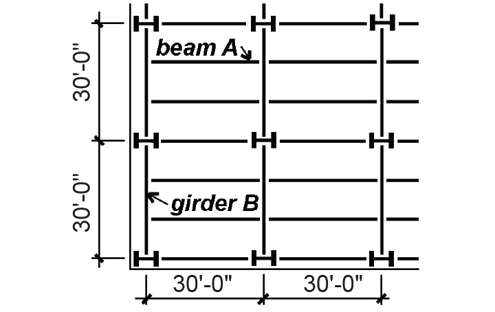
Problem definition. Assume a typical steel structure with corrugated steel deck and concrete slab, tile floor, suspended ceiling system, and allowances for partitions and mechanical ducts, as shown in Figure 2.1. The spandrel girders carry an additional cladding load consisting of a brick and block cavity wall, 12-ft high from floor to floor. Find the dead load distribution on beam A and spandrel girder B.
Solution overview. Find weights of building elements; compute total dead load on beams and girders.
Problem solution
Beam A
1. From Appendix Table A-2.1, find weights of building elements:
a. steel deck, finish floor, ducts and ceiling system = 47 psf.
b. partitions = 8 psf.
c. subtotal = 55 psf.
2. Compute weight per linear foot of beam by multiplying unit weight by tributary area on one linear foot of the beam: 55 × 10 = 550 lb/ft.
3. From Appendix Table A-2.1, assume weight of beam: 40 lb/ft.
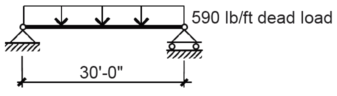
4. Add beam weight to superimposed dead load to get total dead load, D = 550 + 40 = 590 lb/ft, as shown in Figure 2.2.
Girder B
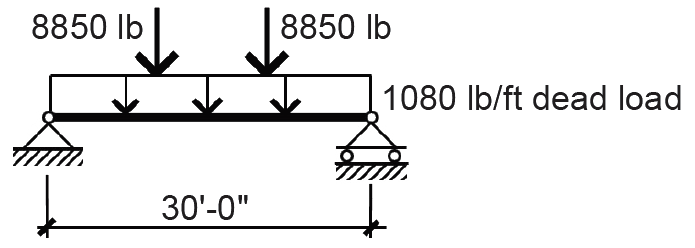
1. Find concentrated dead loads at third points caused by typical beam reactions, equal to the distributed load on the beam times the beam span divided by two: P = 590(30)/2 = 8850 lb.
2. From Appendix Table A-2.1, find weight of cladding = 1000 lb/ft.
3. From Appendix Table A-2.1, assume weight of girder: 80 lb/ft.
4. Add girder weight to cladding weight = 80 + 1000 = 1080 lb/ft.
5. The dead load on the girder consists of the distributed load in addition to the concentrated loads transferred by typical beams, as shown in Figure 2.3.
Dead loads also figure prominently in the evaluation of various environmental loads, such as those caused by wind and earthquakes. Seismic loads, for example, are directly proportional to the inertial mass of the building, so that large dead loads are associated with large seismic forces. The effects of wind, on the other hand, can often be mitigated by the addition of dead load, since overturning and uplift — tendencies that act opposite to the force of gravity — are reduced as the building's weight increases.
© 2020 Jonathan Ochshorn; all rights reserved. This section first posted November 15, 2020; last updated November 15, 2020.