
Jonathan Ochshorn
© 2009 Jonathan Ochshorn.
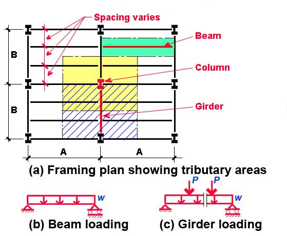
Directions: Enter values for plan dimensions "A" and "B" as shown in Fig. 1(a), and for type of loads. Indicate whether live load reduction is to be considered. Typical loading diagrams for beams and girders are shown in Fig. 1(b) and Fig. 1(c). The concentrated loads, P, shown on the girder diagram correspond to the reactions of the beams framing into the girder. Both beams and girders can have an additional linear dead load added, typically due to self-weight (of the beam itself) and/or loads from curtain wall systems for spandrel beams or girders. Enter the number of beams framing into a typical girder. Doing so automatically adjusts the tributary area for the typical beam.
For columns, it is assumed that tributary areas are the same for all floors. Separate values for roof and floor dead loads can be entered if desired; live loads are assumed to be the same on all floors (with no live loads on roof).
Press "update" button.
More detailed explanations and examples can be found in my text.
Disclaimer: This calculator is not intended to be used for the design of actual structures, but only for schematic (preliminary) understanding of structural design principles. For the design of an actual structure, a competent professional should be consulted.
First posted July 12, 2009 | Last updated June 22, 2010