
Contents | 1. Introduction to structural design |
Introduction to loads | Dead loads | Live loads | Environmental loads |
Structural engineering prescriptions tend to be written in the form of unambiguous mathematical relationships. In fact, the seeming authority of these formulations masks a rather different reality: the entire subject area of structures is littered with fundamental uncertainties. These uncertainties include not only the nature of loads and the strength and stiffness of structural materials in resisting these loads; but also the appropriateness of mathematical models used in design and analysis, and the degree to which actual built structures conform to the plans and specifications produced by their designers. The basic requirements of safety, serviceability and economy depend on how well designers maneuver within this probabilistic environment.
Structural design approaches can be characterized by the extent to which these uncertainties are made explicit. The simplest approach to designing structures uses a single factor of safety to define allowable stresses for a particular material. If actual (i.e., calculated) stresses do not exceed these allowable stresses, the structure is considered to be safe. Rather than using allowable stress, it is also possible to use allowable strength, measured in moment or force units. The allowable, or "available," strength is defined by applying a safety factor to the structural element's so-called "limit state," i.e., to the maximum moment or force it can sustain. Then, the element is designed such that its available strength (the limit state divided by a safety factor) is greater or equal to its required strength (the computed force or moment resulting from the application of loads).
In some cases, the factor of safety is actually given. In steel design, for example, the available strength is determined by dividing the limit-state moment or force by a safety factor. In other cases, for example in timber design, the allowable stress is simply presented as a property of the material, and the degree of safety is hidden from the designer. In all cases, however, it is not possible to "fine tune" the structure's design by considering the relative uncertainty of various load types.
In allowable stress (or allowable strength) design, dead and live loads are simply added together, in spite of the fact that dead loads can be predicted with a higher degree of certainty than live loads. Thus, if two structures carry the same total load, but one structure has a higher percentage of dead load, the structures will have different degrees of safety if designed using the allowable stress method. In fact, the structure with more dead load will be statistically safer, since the actual dead load acting on the structure is more likely to correspond to the calculated dead load than is the case with live load. Allowable stress design is sometimes called working stress design, since the loads used in the method ("service loads") represent what we expect to actually "work" with during the life of the structure.
Load combinations in allowable stress design. To account for the improbability of multiple loads simultaneously acting on a structure at their maximum intensity, most codes provide load reduction factors for various combinations of load types. For example, where several loads are being considered, the "non-dead" loads may be multiplied by 0.75, as long as the total thus calculated does not exceed the dead load together with the largest single additional load considered in the calculations (earthquake loads are sometimes excluded from this provision). The reduction of live loads on relatively large influence areas was discussed previously in this chapter.
A more recent approach to the design of structures explicitly considers the probabilistic nature of loads and the resistance of structural materials to those loads. Instead of regulating the design of structural elements by defining an upper limit to their "working stresses," strength design considers both the limit state of the structural element — typically the strength at which the element fails or otherwise becomes structurally useless — as well as the relative uncertainty of the various loads acting on that element.
Using this method, the required strength of a structural element, calculated using loads multiplied by load factors (that correspond to their respective uncertainties), must not exceed the design strength of that element, calculated by multiplying the strength of the structural element by resistance factors (that account for the variability of stresses, and the consequences of failure). If Q represents the loads and their effects on a structural element, and R represents the resistance, or strength, of that element, then strength design can be schematically represented as follows:
where γi are the load factors (mostly greater than 1.0); φ is the strength reduction factor (smaller than 1.0); and λ is an additional factor (smaller than 1.0) that can be used when multiple load types are assumed to act simultaneously, in which case the likelihood of all loads being present at their maximum intensities is reduced.
Load combinations in strength design. For reinforced concrete designed with the strength method, some commonly used factored load combinations are listed in Appendix Table A-2.7. Multiple combinations of loads are less likely to occur simultaneously at full magnitude; the load factors listed in Appendix Table A-2.7 account for these variable probabilities. The load factor for dead load is sometimes less than zero, since this can represent the more dangerous condition (i.e., the more conservative assumption) where wind or earthquake forces cause overturning or uplift.
Strength design is similar to Load and Resistance Factor Design (LRFD in wood or steel), or "limit state design." In the U.S., strength design is now used almost exclusively in reinforced concrete design; beginning to be widely used in steel design; and not yet commonly used in timber design. In this text, we will use strength design for reinforced concrete, allowable stress design for timber and allowable strength design for steel.
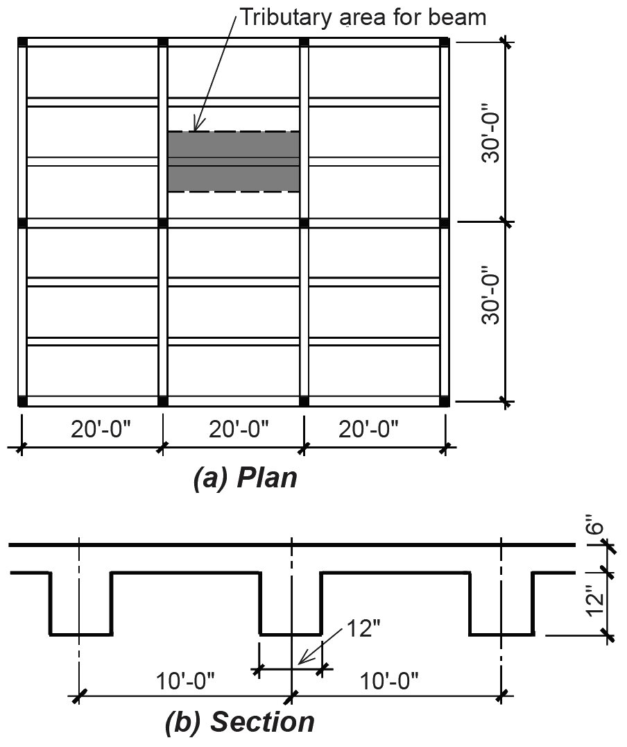
Problem definition. For the "light manufacturing" structure shown in Figure 2.20, assume that the dead load consists of the reinforced concrete floor structure. The weight of the reinforced concrete can be taken as 150 pcf. Find the distributed "design" load on a typical beam for both strength design and allowable stress design.
Solution overview. Find dead and live loads; add loads together for allowable stress design; apply load factors for strength design (strength design is used almost exclusively for the design of reinforced concrete structures).
Problem solution
1. From Appendix Table A-2.2, find live load: L = 125 psf; or, considering the distributed load on a typical beam, L = 125 × 10 = 1250 lb/ft.
1. Find dead load.
a. Slab: (150)(6/12)(10) = 750 lb/ft.
b. Beam: (150)(12/12)(12/12) = 150 lb/ft.
c. Total dead load = 750 + 150 = 900 lb/ft.
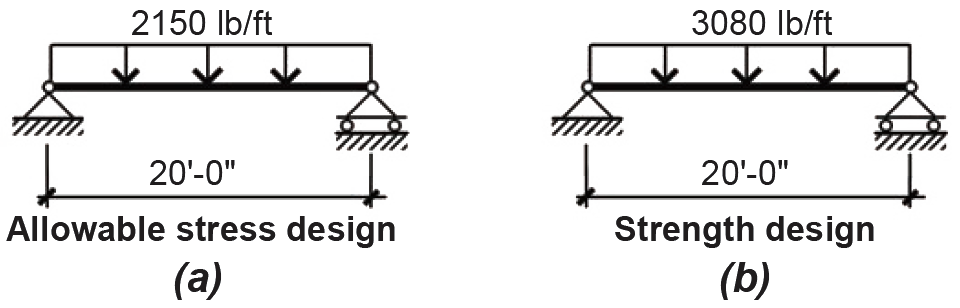
2. Allowable stress design: Total load = D + L = 900 + 1250 = 2150 lb/ft (Figure 2.21a).
3. Strength design: From Appendix Table A-2.7, the total load = 1.2D + 1.6L = 1.2(900) + 1.6(1250) = 3080 lb/ft (Figure 2.21b).
Problem definition. Now, repeat Example 2.6, except change the occupancy to that of a restaurant, and add ceramic tile (weighing 25 psf) to the surface of the slab.
Solution overview. Find dead and live loads; add loads together for allowable stress design; apply load factors for strength design.
Problem solution
1. From Appendix Table A-2.2, find live load: L = 100 psf; or, considering the distributed load on a typical beam, L = 100 × 10 = 1000 lb/ft.
2. Find dead load.
a. Slab: concrete + tile = (6/12)(150)(10) + 25(10) = 1000 lb/ft.
b. Beam: (12/12)(12/12)(150) = 150 lb/ft.
c. Total dead load = 1000 + 150 = 1150 lb/ft.
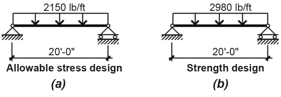
3. Allowable stress design: Total load = D + L = 1150 + 1000 = 2150 lb/ft (Figure 2.22a).
4. Strength design: From Appendix Table A-2.7, the total load = 1.2D + 1.6L = 1.2(1150) + 1.6(1000) = 2980 lb/ft (Figure 2.22b).
Examples 2.6 and 2.7 were admittedly rigged to make a point: even though the total unfactored loads are the same in both cases, the factored loads used in strength design are different, since the proportion of live to dead loads has changed. The allowable stress procedure would result in exactly the same beam design in both cases, whereas the strength method would permit a smaller beam for the restaurant in Example 2.7 (since the total design loads are smaller). However, according to the probabilistic logic of strength design, even though the restaurant beams are smaller than the beams for light manufacturing, the degree of safety would be the same for both beams.
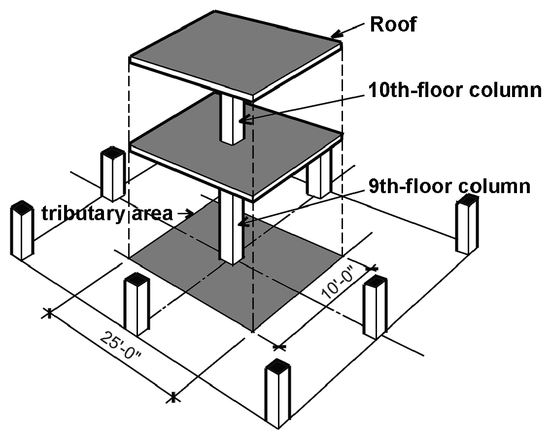
Problem definition. Assuming strength design, find the various combinations of load acting on the 9th- and 10th-floor columns shown in Figure 2.23. Assume that the dead load for each floor level is 40 psf, the live load for the 10th floor is 60 psf, the roof live load, Lr (maintenance, etc.), is 20 psf, and the wind load acting on the roof is 30 psf (acting upward). The tributary area is 25 × 10 = 250 ft2 per floor, as shown in Figure 2.23.
Solution overview. Find loads (including live load reduction coefficient); compute load combinations; identify critical (governing) combinations.
Problem solution
10th-floor column:
1. Find loads:
a. D = 250(40) = 10,000 lb = 10 kips.
b. Lr = 250(20) = 250(20) = 5000 lb = 5.0 kips.
c. W = 250(–30) = –7500 lb = –7.5 kips.
2. From Appendix Table A-2.7 (strength design), compute load combinations:
a. 1.4D = 1.4(10) = 14 kips.
b. 1.2D + 1.6L + 0.5(Lr or S) = 1.2(10) + 0 + 0.5(5) = 14.5 kips.
c. 1.2D + 1.6(Lr or S) + (0.5L or 0.8W) = 1.2(10) + 1.6(5) + 0.8(–7.5) = 14 kips.
d. 1.2D + 1.6W + 0.5L + 0.5(Lr or S) = 1.2(10) + 1.6(–7.5) + 0 + 0.5(5) = 2.5 kips.
e. 1.2D + 1.0E + 0.5L + 0.2S = 1.2(10) + 0 + 0 + 0 = 12 kips.
f. 0.9D + 1.6W = 0.9(10) + 1.6(–7.5) = –3 kips.
g. 0.9D + 1.0E = 0.9(10) + 0 = 9 kips.
3. Conclusions: For the 10th-floor column, the critical load combinations are 14.5 kips from live and dead load plus roof live load (combination b); and –3 kips from dead and wind load (combination f). The negative force due to wind uplift must be considered since it places the upper level column in tension. In equations d, d, and e, the live load factor is taken as 0.5 (see Note 2 in Appendix Table A-2.7).
9th-floor column:
1. Find loads:
a. D = 250 (40) × 2 floors = 20,000 lb = 20 kips.
b. Lr = 250(20) = 250(20) = 5000 lb = 5.0 kips.
c. The live load reduction coefficient can be found from Appendix Table A-2.2 and is equal to: 0.25 + 15/ = 0.72.
d. L = (250 × 60)(reduction coefficient) = (250 × 60)(0.72) = 10,800 lb = 10.8 kips.
e. W = 250(–30) = –7500 lb = –7.5 kips.
2. From Appendix Table A-2.7 (strength design), compute load combinations:
a. 1.4D = 1.4(20) = 28 kips.
b. 1.2D + 1.6L + 0.5(Lr or S) = 1.2(20) + 1.6(10.8) + 0.5(5) = 43.78 kips.
c. There are two choices here:
(1) using W: 1.2D + 1.6(Lr or S) + (0.5L or 0.8W) = 1.2(20) + 1.6(5) + 0.8(–7.5) = 26.0 kips; or
(2) using L: 1.2D + 1.6(Lr or S) + (0.5L or 0.8W) = 1.2(20) + 1.6(5) + 0.5(10.8) = 37.4 kips.
d. 1.2D + 1.6W + 0.5L + 0.5(Lr or S) = 1.2(20) + 1.6(–7.5) + 0.5(10.8) + 0.5(5) = 19.9 kips.
e. 1.2D + 1.0E + 0.5L + 0.2S = 1.2(20) + 0 + 0.5(10.8) + 0 = 29.4 kips.
f. 0.9D + 1.6W = 0.9(20) + 1.6(–7.5) = 6 kips.
g. 0.9D + 1.0E = 0.9(20) + 0 = 18 kips.
3. Conclusions: For the 9th-floor column, the critical load combination is 43.78 kips from live and dead load plus roof live load (combination b). No combination of loads places the column in tension. In equations c, d, and e, the live load factor is taken as 0.5 (see Note 2 in Appendix Table A-2.7).
In a reinforced concrete structure, columns typically are also subjected to bending moments due to their continuity with beams, girders or slabs. Where the combined effects of axial loads and bending moments are accounted for — something that is beyond the scope of this book — the axial loads computed from other load combinations (together with the bending moments associated with them) might turn out to be critical.
© 2020 Jonathan Ochshorn; all rights reserved. This section first posted November 15, 2020; last updated November 15, 2020.