Contents | 1. Introduction to structural design | 2. Loads | 3. Wood | 4. Steel |
Introduction to reinforced concrete | Material properties | Sectional properties | Design approaches |
Reinforced concrete buildings are built twice: first as an "inverse" building in which the desired content is made void and the space around this content is actually constructed; and then again as the real, intended structure consisting of concrete reinforced with deformed steel rods. Of course, the first building is not really a building at all, but rather the formwork in which the reinforced concrete building is cast. Still, the construction of extensive formwork as the inverse condition of the intended concrete structure has significant ramifications, not only in terms of structural costs but also in terms of formal constraints that are imposed on the concrete design by the necessity of first constructing the inverse forms from some other material.
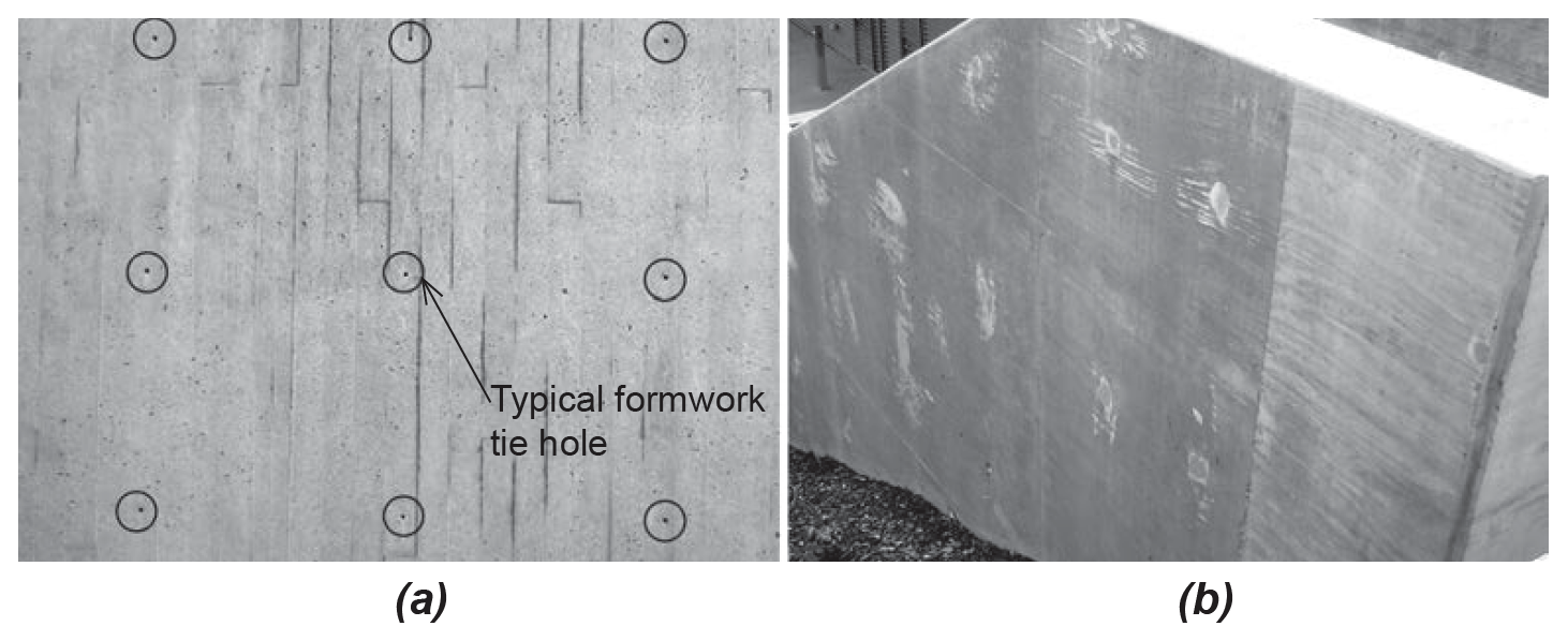
Historically, lumber was the primary material used to create forms into which concrete is placed, or cast. Now, other materials are also used, especially metal (reusable) forms and plywood (rather than boards), but also plastics and fiberglass. Formwork must be structurally able to withstand the lateral pressure of the "wet" concrete before it cures (hardens). Metal formwork ties are often provided for this purpose, leaving small circular marks in the surface of the concrete that may be organized and detailed for aesthetic purposes in so-called "architectural" concrete (i.e., concrete where the architect and client care about the surface qualities as in Figure 5.5a), or simply filled with grout in more utilitarian applications (or where the sloppiness of the finish is actually consistent with the aesthetic intentions as in Figure 5.5b).
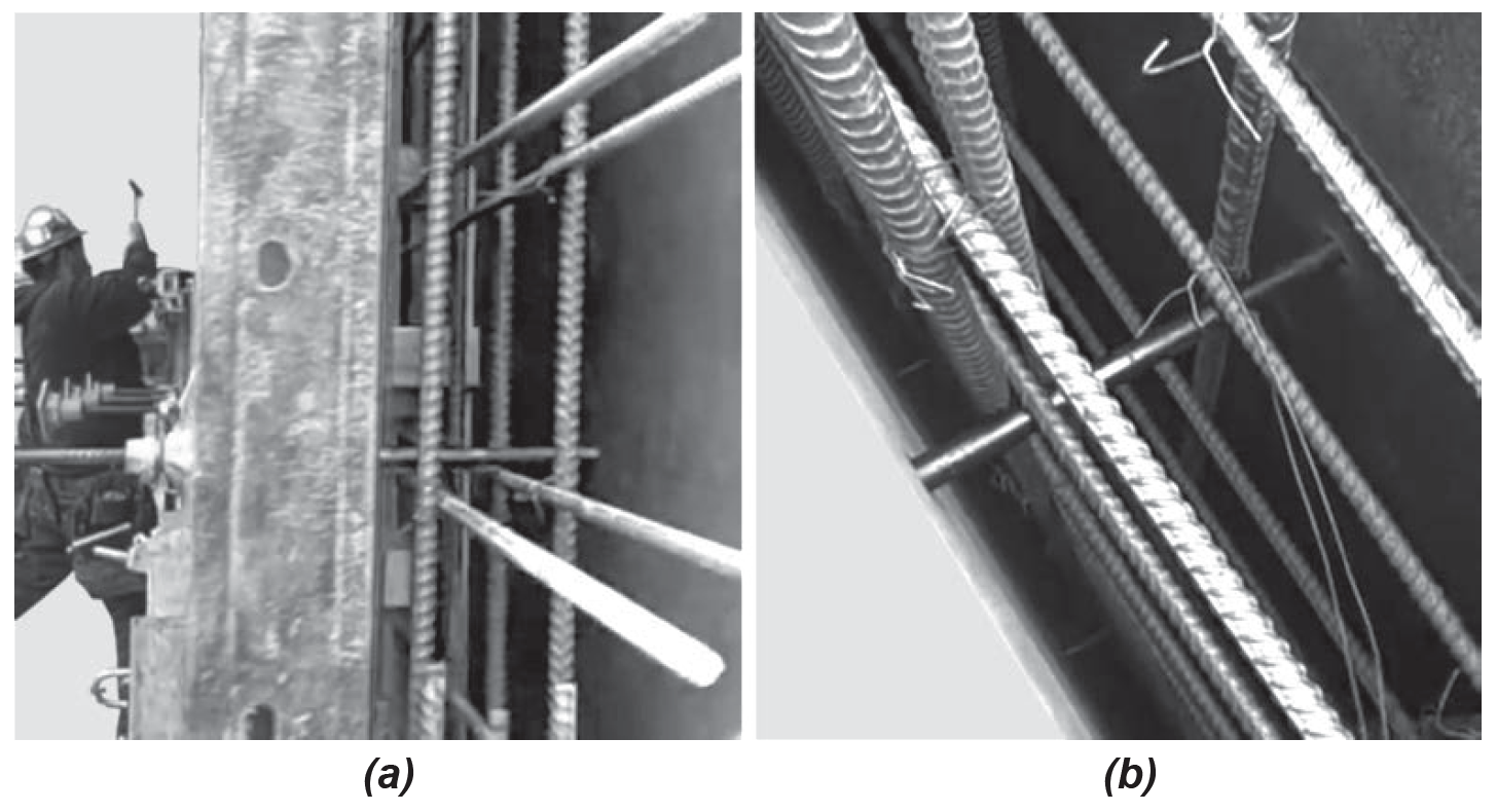
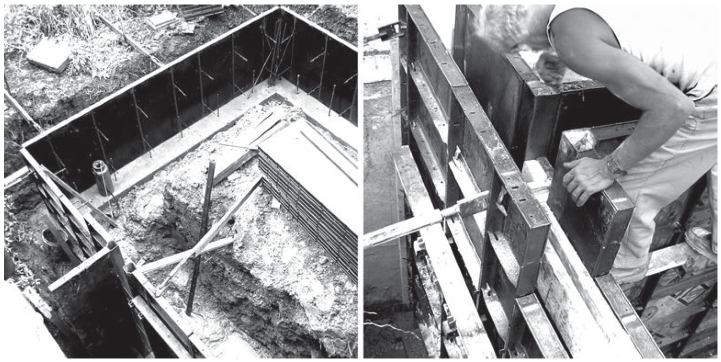
These ties can be configured so that they simultaneously support reinforcing bars, which are placed in the forms before the concrete is cast (Figure 5.6).
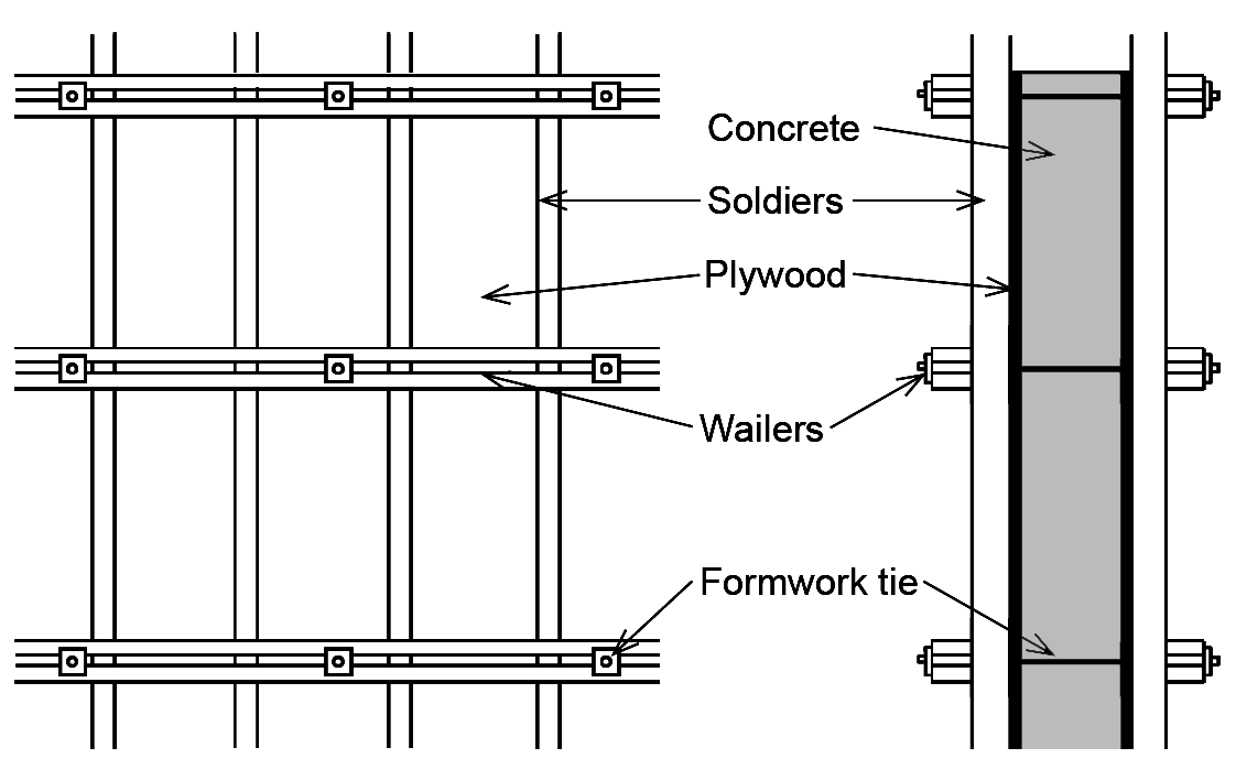
Traditional formwork structures consist of ordinary dimension lumber arrayed in a gridded pattern of soldiers (vertical elements) and wailers (horizontal elements) that support two wooden surfaces (boards or plywood) between which a concrete wall is cast (Figure 5.7).
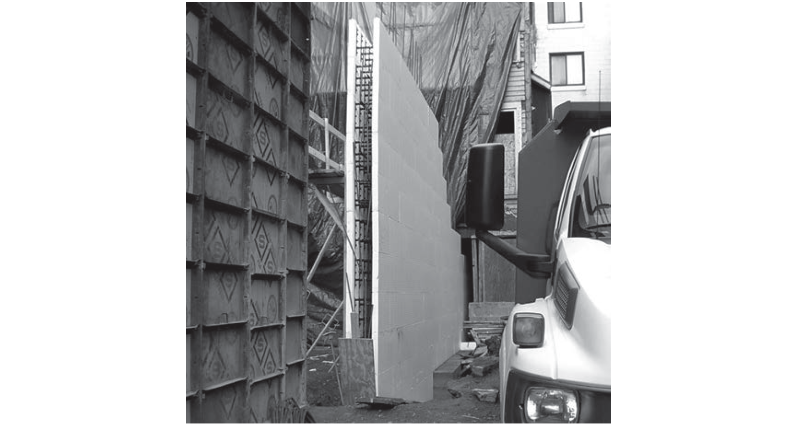
Reusable metal forms are also commonly employed (Figure 5.8) and, in applications where concrete walls need to be insulated in any case, insulating concrete forms (ICFs) — consisting only of rigid insulation held together with metal ribs instead of formwork ties — can be used instead of wood- or metal-based systems of formwork (Figure 5.9). In such systems, the insulation-as-formwork remains in place permanently.
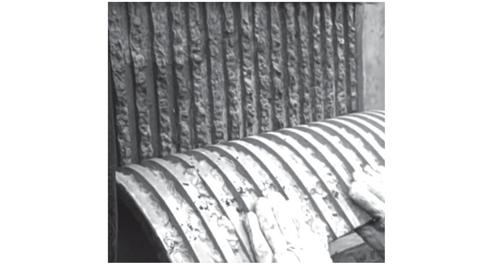
When reinforced concrete elements are exposed, the surface quality of the concrete may be problematic, since it is the cement — the least visually interesting component of the concrete — that rises to the surface. Many compensatory strategies have been employed to turn concrete into something more visually compelling. To remove the mottled gray surface of cement and expose aggregate, the surface can be sandblasted or acid etched; or the materials comprising the formwork itself can be carefully chosen to impart on the cement a mirror image of whatever the forms were made from — examples include the carefully spaced wooden boards shown in Figure 5.5a, or a rougher, "brutalist" aesthetic deriving from the use of construction-grade lumber, plywood, or even metal forms. Alternatively, form liners can be inserted into formwork to impart a texture or pattern onto the concrete that is independent of the formwork material itself (Figure 5.10).
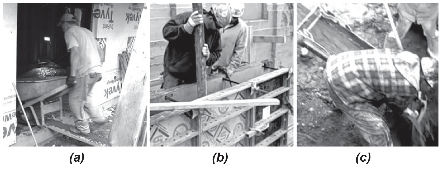
Concrete is moved from mixer to formwork by various means, including wheelbarrows, buckets, pumping, or mere gravity (Figures 5.11 and 5.12).
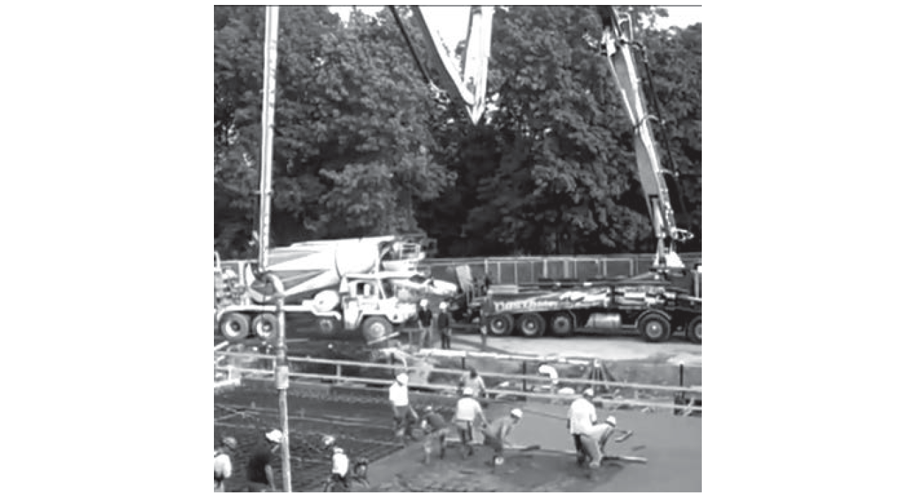
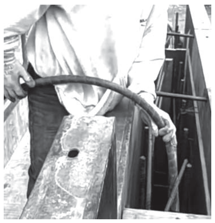
A danger in such movement is segregation, where heavier aggregate settles and water rises. Concrete is placed or cast rather than poured, although the latter term has insinuated itself into common construction vocabularies, and cannot be entirely avoided. In any case, try to say "cast-in-place" instead of "poured-in-place." To make sure that concrete has reached all parts of the formwork, it is often vibrated with special tools (yes, vibrators are used — see Figure 5.13). This prevents honeycombing (where voids appear after the formwork is removed). Concrete should be protected from moisture loss (evaporation) for at least 7 days, by sprinkling water on its surface, or by covering it with sheets such as polyethylene.
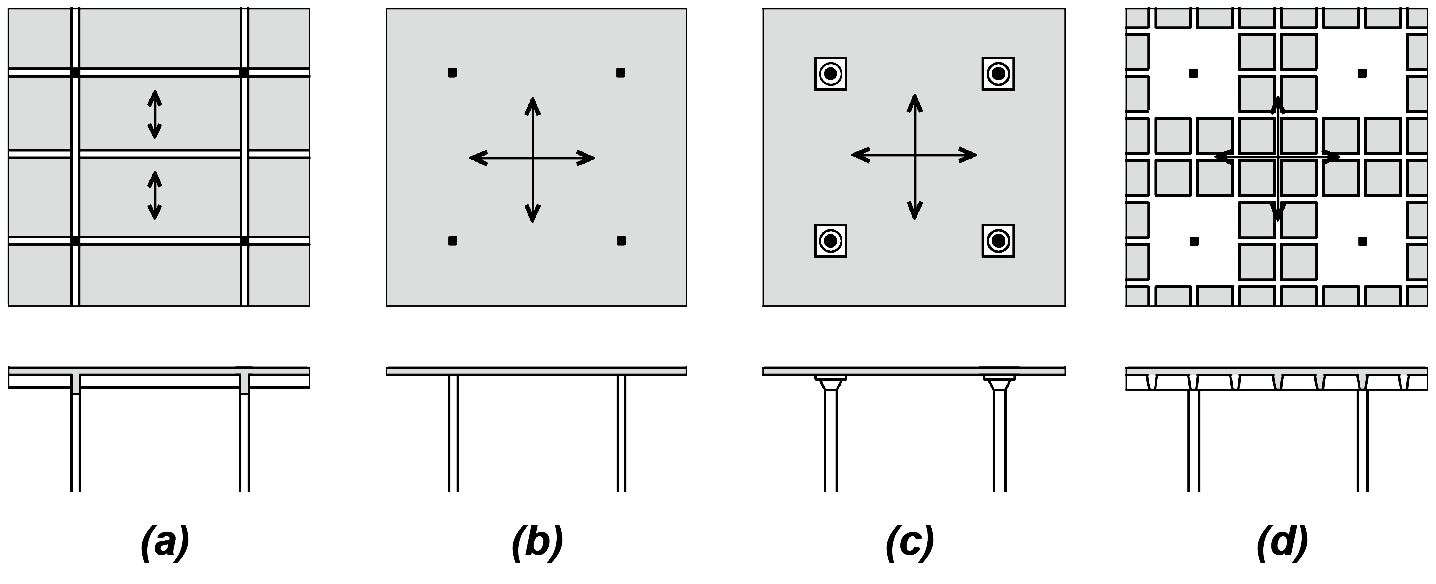
Reinforced concrete can be cast into an infinite variety of shapes, subject only to the laws of statics and the difficulty (expense) of creating the forms into which the concrete is cast. At one extreme can be found reinforced concrete structures whose forms are entirely unique, idiosyncratic, and expressive; at the other extreme are concrete structures made entirely from rationalized and reusable forms organized to produce buildings with relatively simple and repetitive geometries. In the latter category are framed structures consisting of columns and slabs, either with or without the hierarchically intermediate girders and beams characteristic of wood and steel structures. Reinforced concrete girders are never really omitted in such systems, but they can be subsumed within the thickness of floor or roof slabs so that the structure appears to consist only of a slab resting directly on columns. Figure 5.14 shows common structural slab systems for reinforced concrete-framed structures.
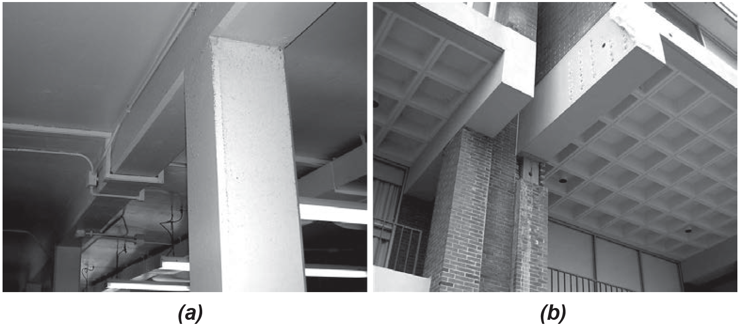
Examples of one-way slab systems and grid (waffle) slab systems can be seen in Figure 5.15. Procedures for the design of reinforced concrete columns, one-way slabs, beams, and girders will be discussed later in this chapter.
© 2020 Jonathan Ochshorn; all rights reserved. This section first posted November 15, 2020; last updated November 15, 2020.