
Contents | 1. Introduction to structural design | 2. Loads | 3. Wood | 4. Steel |
Introduction to reinforced concrete | Material properties |
Because cast-in-place, or site-cast, concrete is literally made at the building site, the only real constraint on the sizes and shapes of concrete structural elements is the willingness of architects, engineers, owners, and contractors to design the structure, and assemble the formwork into which the concrete and reinforcement is placed. The history of reinforced concrete structures is thus filled with elaborate, structurally-expressive, one-of-a-kind projects in which the "plasticity" of the material is exploited. The costs of formwork can be significant, though, and many reinforced concrete structures are designed to minimize these costs by rationalizing the dimensions of the various concrete elements, in part by reusing standardized forms where possible. For these structures, the outside dimensions of beams, slabs and columns are often rounded up to the nearest ½ in., 1 in. or even-numbered inch, depending on how big the element is. Slabs 6 in. thick or less are rounded up to the nearest ½ in.; thicker slabs are rounded up to the nearest inch. The cross-sectional dimensions of beams and columns are rounded up to the nearest 1 in. or even-numbered inch (see Appendix Table A-5.1).
Reinforcing bar (rebar) spacing in reinforced concrete beams and columns is constrained by several factors. First, bars must be far enough apart so that aggregate in the concrete mix can pass freely between them — in general the largest aggregate size must be no more than ¾ the minimum distance between bars. Looked at from the opposite point of view (that is, with the maximum aggregate size set), the minimum space between bars must be 1⅓ times greater than the largest aggregate. For 1 in. aggregate, the minimum clear bar spacing would be 1⅓ in., or approximately 1½ in. Additional requirements relate bar spacing to bar size: for beams, the spacing must be not less than the nominal bar diameter, or 1 in.; for columns, the spacing must be not less than 1½ times the nominal bar diameter, or 1½ in.
In the U.S., rebars were designated and marked by a number corresponding to the bar's nominal diameter multiplied by eight: for example, a bar with a nominal diameter of ½ in. would be designated as a No. 4 bar (since ½ × 8 = 4). In an increasingly international marketplace, these designations have been replaced with SI (international system) units, so the old No. 4 bar is now designated with the number 13 (since ½ in. = 12.7 mm, or approximately 13 mm). Even so, the old U.S. system of bar numbering is still used by the American Concrete Institute (ACI) in its structural concrete codes and commentaries, and will be used in this text. Side-by-side listings of new and old designations can be found in Appendix Tables A-5.2 and A-5.3.
For all commonly used beam reinforcing (No. 11 bars or smaller) and with aggregate no larger than 1 in., the minimum bar clear spacing requirement can be set at 1½ in. for beams. For column reinforcing of No. 8 bars or smaller (that is, 1 in. diameter or smaller) and with aggregate no larger than 1 in., the minimum spacing requirement can also be set at 1½ in. for columns. However, for bar sizes larger than No. 8, the spacing requirement increases to 1½ times the nominal bar diameter.
The implications for minimum width or diameter of reinforced concrete columns and beams are shown in Figure 5.4 and summarized below, assuming 1½ in. cover and ½ in. diameter ties, stirrups, or spiral reinforcement. The specific function of these reinforcement types is explained later in this chapter (ties and spirals for columns; stirrups for beams).
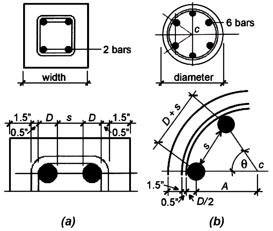
1. For beams (with bar size of No. 11 or smaller) and for columns with bar size of No. 8 or smaller, with two bars along the beam or column face: the minimum width (in.) = 5.5 + 2D, where D is the bar diameter (in.). For beams or columns with more than two bars in a line, add 11/2 in. + D for each additional bar.
2. For columns with bar size larger than No. 8, with two bars along the column face, the minimum width (in.) = 4 + 3.5D, where D is the bar diameter (in.). For columns with more than two bars in a line, add 2.5D for each additional bar.
1. For spiral columns with six bars, No. 8 or smaller: the minimum column diameter (in.) = 7 + 3D, where D is the bar diameter (in.). For columns with bar sizes larger than No. 8: the minimum diameter = 4 + 6D.
2. Minimum widths for rectangular beams and columns, and minimum diameters for spiral columns, are given in Appendix Table A-5.3.
© 2020 Jonathan Ochshorn; all rights reserved. This section first posted November 15, 2020; last updated November 15, 2020.