
Contents | 1. Introduction to structural design | 2. Loads | 3. Wood | 4. Steel |
Introduction to reinforced concrete | Material properties | Sectional properties | Design approaches | Construction systems | Tension elements | Columns | Beams |
Reinforced concrete elements are not ordinarily "connected" in the usual sense of the term; rather, they are most often cast together into a monolithic assembly. Of course, there are construction joints between sections of the structure cast separately, but even at such joints, opposite faces of concrete brought together in compression bear against each other just as if they had been monolithically cast; and steel reinforcement in tension is made to extend through each construction joint so that tensile forces in the bars continue from one side of the joint to the other.
The following discussion therefore does not include any reference to the types of welds, bolts, screws, or nails commonly found in wood or steel construction, where discrete structural elements subjected to tension, compression, or bending must be explicitly connected in order to function together as a coherent structural system. Instead, two "quasi-connections," both typical of reinforced concrete construction, shall be examined: the end condition of a continuous beam, and the lapped splicing of reinforcing bars where the bottom of one column is cast against the top of another column.
The fact that much reinforcing steel is subjected to tension raises an important question: what prevents such steel bars from being pulled out of, or slipping within, the concrete into which they have been placed? As can be seem in Figure 5.48, any bending of a structural element literally stretches the tension region while the compression region shortens.
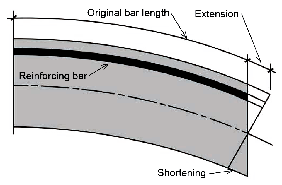
If the surface between the reinforcing bars and adjacent concrete were smooth and frictionless, the bars would remain "unstretched" as the beam bent; in general, it is the bond between the steel bars and concrete that guarantees that such slippage will not occur. This bond is primarily a result of bumps, or deformations, placed on the surface of the reinforcement that create a mechanical interlocking of the steel and concrete surfaces, as shown schematically in Figure 5.49.
The strength of this bond, per unit of bar length, has been measured experimentally, so the total necessary bar length required to resist any tendency for the bar to be pulled through the concrete can be determined for any given tension stress. This required bar length is called the development length, ld, and is shown in Equation 5.29 for No. 7 or larger uncoated bars with normalweight concrete and adequate bar spacing, or adequate spacing plus confinement with ties or stirrups, to prevent splitting of the concrete. Specifically, as illustrated in Figure 5.50, the bars must have a clear space between them at least equal to twice the bar diameter, that is, at least equal to 2db, and clear cover at least equal to the bar diameter, db.
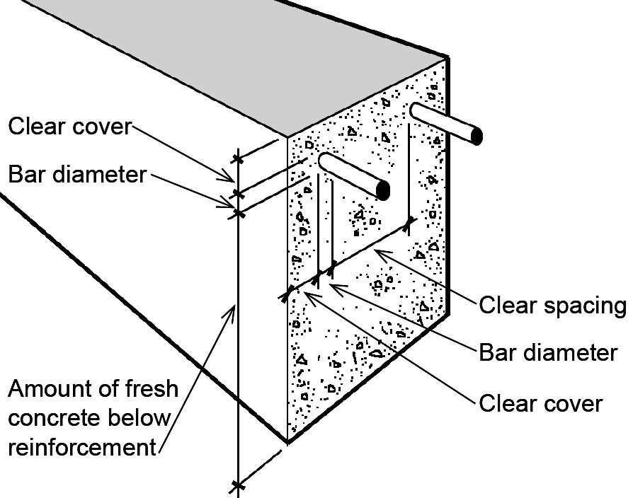
Alternatively, if adequate stirrups or ties are used throughout the development length region to confine the bars and prevent splitting of the concrete, the minimum clear spacing requirement may be reduced to db.
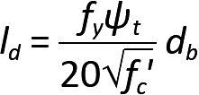
In Equation 5.29, ld is the development length for tension (in.), fy is the yield stress of the steel reinforcement (psi), fc' is the compressive strength of the concrete (psi), ψt is a coefficient equal to 1.0 except when there is at least 12 in. of freshly cast concrete below the steel bars, in which case ψt = 1.3 (accounting for the negative impact on the bond between steel and concrete caused by rising air and water within a large mass of freshly-cast concrete), and db is the reinforcing bar diameter (in.). Some disclaimers: Where fy is greater than 60 ksi, the development length increases by 15 percent or 30 percent for Grade 80 and Grade 100 reinforcement respectively. The square root of fc' in the equation cannot be taken greater than 100, an upper limit that only applies to concrete strengths greater than 10,000 psi. Equation 5.29 is often conservative, and a more complex version in the ACI Code might allow development lengths that are as much as 67% shorter under certain circumstances. On the other hand, using the simplified equation, but where the minimum conditions for spacing and stirrups (or ties) described above are not met, the development length in Equation 5.29 must be increased by a factor of 1.5. Where the bar size is smaller than No. 7, the development length is multiplied by 0.8. In no case may the development length be less than 12 in. Typical values for development length are tabulated in Appendix Table A-5.10 for common bar sizes.
Development length is influenced primarily by three factors: assuming adequate bar spacing and/or ties to prevent splitting of the concrete, the required development length becomes larger if the tensile strength of the concrete decreases (concrete's tensile strength is proportional to the square root of its compressive strength); the required development length also increases if the stress in the bar increases (that stress being at most equal to the yield stress of the steel); and the development length increases as well if the surface area of the bar decreases (the surface area being proportional to the bar diameter). These three parameters can all be found in Equation 5.29.
If we imagine an isolated and discrete concrete beam within a continuous concrete structure, it is easier to see where and how the concept of development length becomes important. As can be seen in Figure 5.51, a typical reinforced concrete beam-girder "connection" must resist the shear force and bending moment that occur at the surface where they come together. The shear force is resisted through the shear resistance of the concrete itself, the longitudinal steel bars, and the steel ties or stirrups provided for that purpose (the latter not shown in Figure 5.51 for clarity).
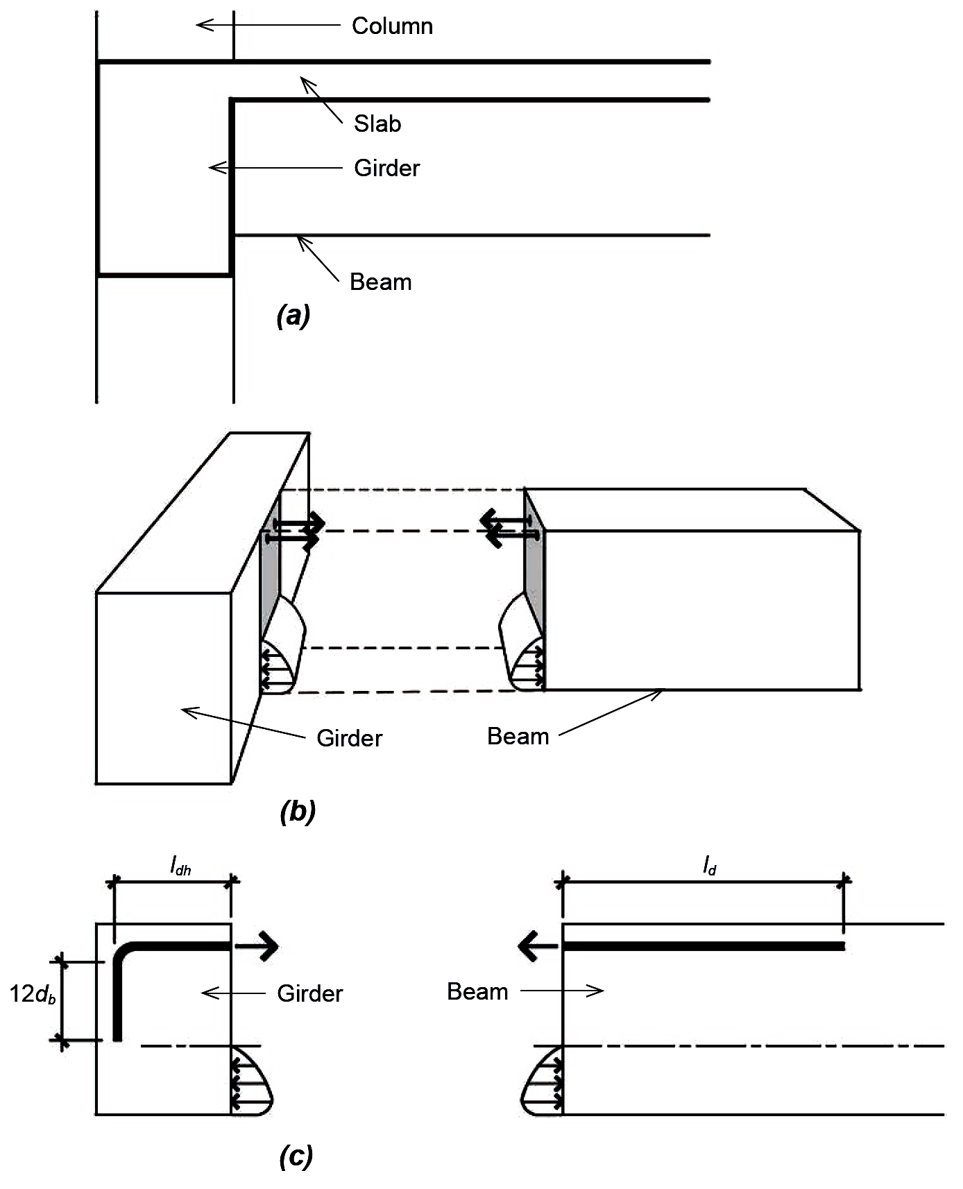
The bending moment, in turn, is resolved into a compressive force (the resultant of the stress distribution shown below the neutral axis for "negative" bending) and a tensile force (carried by the longitudinal steel reinforcement shown above the neutral axis). The compressive force presents no particular problems, as the concrete in the beam "pushes" against the concrete in the girder. The tensile force, however, could pull the bars out of the girder and beam, unless those bars develop sufficient bond with the concrete to resist that tendency or are otherwise anchored into the concrete. In the case of the beam, sufficient space is available to develop that bond strength by making sure that the bars extend into the beam for a distance at least as great as the required development length, ld (see Equation 5.29). For an exterior girder, however, it is likely that sufficient space is not available, and a 90° or 180° hook is often required. As shown in Figure 5.51c, a 90° hook must be extended a distance of 12db below the bent portion of the bar, which in turn is defined by an inner radius that cannot be less than 3db for bars smaller than No. 9; 4db for No. 9, No. 10, and No. 11 bars; and 5db for No. 14 and No. 18 bars. In these guidelines, db refers to the bar diameter. The required development length for such hooks, ldh, is given by the following equation for uncoated bars and normalweight concrete, with the most conservative assumptions regarding confinement and cover for the hooked bars:
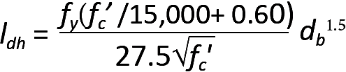
In this equation, ldh is the development length for hooks (in.), fy = the yield stress of the steel reinforcement (psi); fc' is the compressive strength of the concrete (psi); and db is the bar diameter (in.). In no case may the development length for a hook be less than 8db or 6 in. Typical values are tabulated in Appendix Table A-5.11 for common bar sizes.
It is possible to reduce this length if certain requirements are met that increase the level of confinement of the hook or provide more concrete cover, making it less likely to split the concrete: First, the tabular values for development length can be divided by 1.6 if the centerline spacing between hooked bars is at least 6db or if the total area of ties or stirrups confining the hooked bars is not less than 0.4 times the total area of the hooked bars. Second, the tabular values for development length can be divided by 1.25 if the cover on the side of the hooked bars (i.e., perpendicular to their longitudinal direction) is at least equal to 6db or if the hooked bars are inside a column core with side cover at least equal to 2.5 in. Both of these modifications to development length for hooked bars can be taken if both criteria are met.
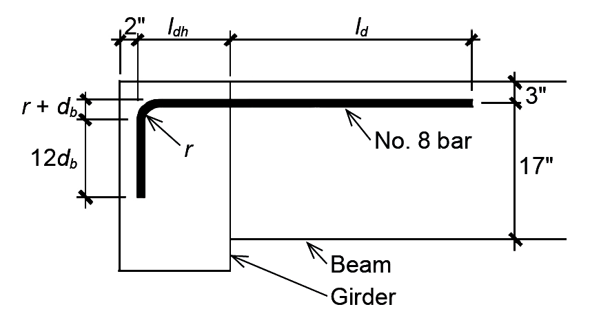
Problem definition. A reinforced concrete beam frames into an exterior girder, as shown in Figure 5.52, and the negative moment at the connection is resisted using No. 8 bars with 6 in. clear spacing between them. The required area for each bar = 0.74 in2. As the beam frames into a girder, it can be assumed that there is at least 6 in. of cover on the side of the hooked bars. Assume fc' = 4000 psi and fy = 60,000 psi. Find the required development length, ld, of the bars within the beam, the hook development length, ldh, and hook extension beyond the bend, within the girder.
Solution overview. Find the nominal development lengths for a No. 8 bar, using 4000-psi concrete, in Appendix Table A-5.10 (for the beam) and Appendix Table A-5.11 (for the hook in the girder). Multiply these base values by the appropriate factors shown in the notes below each table.
Problem solution
1. The nominal development length required for the No. 8 bar in the beam is 62 in. (Appendix Table A-5.10). This value is not divided by 1.3 (see Note 2) and also can be reduced by the ratio of required steel bar area to provided steel bar area = 0.74/0.79 = 0.937 (see Note 3), so that the final value for the required development length, ld = 62(0.937) = 58.1 in. or, rounded up to the nearest inch, 59 in. The required area for each bar = 0.74 in2 was given (or otherwise would be computed); the value for the provided steel bar area is simply the actual area of a No. 8 bar (see Appendix Table A-5.2). The computed development length exceeds the absolute minimum of 12 in. (see Note 5 in the table).
2. The nominal development length for the 90-degree hook in the beam is 30 in. (Appendix Table A-5.11). This value can be modified as follows: it can be divided by 1.6 since the 6 in. centerline spacing of the hooked bars is no less than 6db = 6 in. (see Note 4 in Appendix Table A-5.11); and it can be divided by 1.25 since the side cover is no less than 6db (see Note 5 in Appendix Table A-5.11). These reductions are cumulative, so the required development length for the hooked bar = 30 / (1.6 × 1.25) = 15 in. The actual dimensions of the girder would need to be able to accommodate this required length. The computed development length for hooks exceeds the two absolute minimums (see Note 8 in Appendix Table A-5.11): 8db = 8(1.0) = 8 in., or 6 in. Checking the minimum radius and minimum length of the "vertical" portion of the hook (see Note 5 in the table), we see that the required extension of the bar below the bend is 12db = 12(1.0) = 12 in. and the minimum inner radius for a No. 8 bar is 3db = 3(1.0) = 3 in.
There are two other requirements for tension reinforcement in continuous beams. First, for so-called positive-moment reinforcement — where tension occurs at the bottom of reinforced concrete beams — one-fourth of the rebars need to be extended at least 6 in. into the supports at each end of the beam. Second, for negative-moment reinforcement — where tension occurs at the top of the beam, typically in the vicinity of supports — at least one-third of the rebars need to extend beyond the point of inflection (where the negative moment becomes zero and the curvature changes from negative to positive) a distance of either d, 12db, or ln / 16, whichever is greater: d is the effective depth of the beam; db is the rebar diameter; and ln is the clear span, measured between the faces of supports.
For a steel reinforcing bar in compression, much of the stress in the steel can be transferred to the concrete through direct bearing of the bar end on the concrete. For that reason, the required development length in compression, ldc, is smaller than that required when bars are stressed in tension, and is given by the greater of the following values:
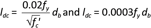
In these equations, ldc is the development length (in.) for normalweight concrete in compression; fy = the yield stress of the steel reinforcement (psi); fc' is the compressive strength of the concrete (psi); and db is the bar diameter (in.). If lightweight concrete is used, the values for development length must be multiplied by 1.333. As with bars in tension, it is possible to reduce this required length by multiplying the greater value found in Equation 5.31 by the ratio of required steel bar area to provided steel bar area. In addition, the required development length may be multiplied by 0.75 in columns with adequate spirals or ties (specifically, with a minimum ¼ in. spiral at no more than a 4 in. pitch; or with No. 4 ties spaced at no more than 4 in. on center). In no case can the development length for compression be less than 8 in. Typical values are tabulated in Appendix Table A-5.12 for common bar sizes.
Since the length of reinforcing bars is limited by manufacturing and transportation constraints, it is often necessary to splice them together, at least in cases where the continuity assumed in design indicates lengths greater than those available from a single bar. While it is possible to weld bars together, or to use special mechanical splicing devices, the most common method for creating continuity between two bars in tension is by lapping them a sufficient distance so that tensile stresses can be transferred through the bond developed between the steel bars and adjacent concrete. For virtually all tension splices, the required lap distance is taken as 1.3ld, where the development length, ld, is defined as in Equation 5.29 (or as tabulated in Appendix Table A-5.10), except that the 12 in. minimum length for ld does not apply (but there is still a minimum splice length of 12 in.), and a reduction of the development length based on the ratio of provided to required steel area is not permitted. There are some limits placed on larger bar sizes: No. 14 and No. 18 bars cannot be lap spliced in tension.
Columns are almost always cast floor by floor, with longitudinal reinforcement left extending vertically beyond the current floor level, so that it can be spliced into the column steel for the next floor being cast. For fy ≤ 60 ksi and fc' ≥ 3000 psi, the required lap distance for compression is taken as:
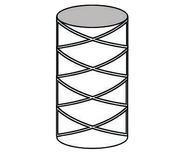
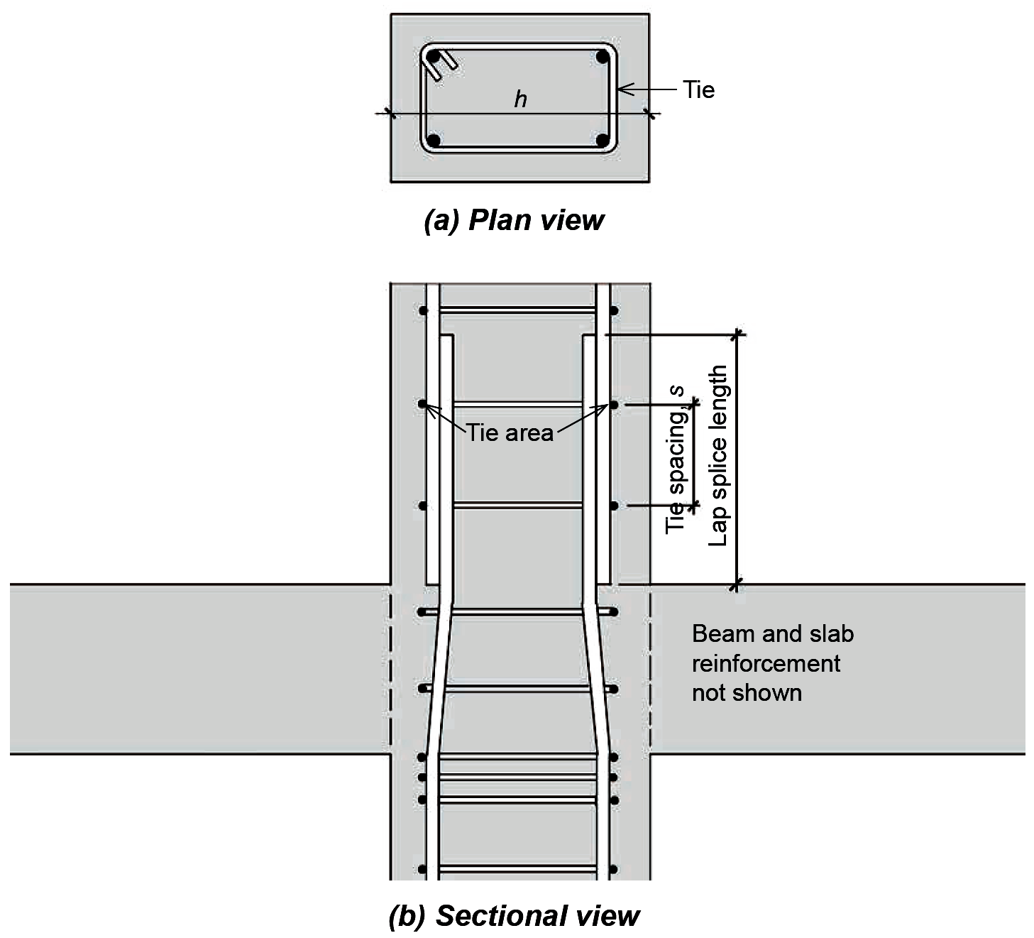
This required lap distance equals 30db for 60 ksi steel bars, with an absolute minimum lap distance of 12 in. For rebars with fy > 60 ksi, the required compressive lap distance is increased to (0.0009fy – 24)db or, only for rebars with fy > 80 ksi, to the larger of (0.0009fy – 24)db and the required tension lap splice distance described above. In all these equations, fy is the yield stress of the steel reinforcement (psi); fc' is the compressive strength of the concrete (psi); and db is the bar diameter (in.). It should be emphasized that in many reinforced concrete columns, especially those explicitly designed to resist bending moment as well as compressive force, a given lap splice may need to resist tension, compression, or both tension and compression, under different loading scenarios. For bars that resist only compression, and where confinement is provided by ties or spirals, it is possible to create splices, not by lapping the bars, but instead by placing their ends in contact so that they bear directly upon each other. However, even in such cases where no tension is anticipated, all columns must maintain some ability to resist unexpected tension forces, so that either additional "tension" steel must be provided in such cases, or else compressive lap splices must be used (since compressive lap splices provide sufficient resistance to unexpected tension forces in the bars). The required length of column lap splices in compression may be reduced where sufficient confinement, in the form of ties or spirals, is provided. Specifically, where the bar area of a tie (taken as the total tie area cut in section, as shown in Figure 5.53) is greater or equal to 0.0015(h × s) — where h is the greater column cross-sectional thickness in inches, and s is the tie spacing in inches — the required lap distance may be multiplied by 0.83; with spirals, the required lap length may be multiplied by 0.75. In any case, the lap length can never be taken less than 12 in. Limits placed on larger bars are relaxed somewhat for lap splices in compression: No. 14 and No. 18 bars cannot be lap spliced to each other, but may be lap spliced to No. 11 and smaller bars. In cases where two different bar sizes are lap spliced together in compression, the required splice length is found by (1) computing the required development length for the larger bar, (2) computing the required lap splice length for the smaller bar, and (3) using the larger of these two values.
For a column resisting only compressive forces, the required lap length is determined for the bars originating in the upper column; the bars extended upwards from the lower column that terminate in the upper column must satisfy the requirements for compressive development length (Equation 5.31). In practice, the larger of these two criteria (compressive development length for the lower bars and required lap splice length for the upper bars) determines the minimum splice length. Since loads typically are smaller in upper-level columns, it is possible that smaller bars sizes can be used in the upper columns; these smaller bars can be spliced with larger bars extending upward from the lower column. In such cases, different bar diameters, db, must be used in determining lap splice length and development length.
Problem definition. A 12 in. × 16 in. reinforced concrete column is configured as shown in Figure 5.53. The longitudinal (vertical) bars in the lower column consist of four No. 9 bars, which extend into the upper column. Four No. 8 bars originate in the upper column, and are spliced to the lower column bars as shown. The longitudinal steel is confined by No. 3 ties spaced at 9 in. on center. Assuming only compressive stress in the column, with fy = 60 ksi and fc' = 3000 psi, what is the required splice length?
Solution overview. Find the compressive lap splice length based on the diameter of the No. 8 bars in the upper column. Find the required compressive development length based on the No. 9 bars extended into the upper column. Use the larger of these two values for the column splice length.
Problem solution
1. Lap splice. From Equation 5.32, the minimum lap splice length for the No. 8 bars = 0.0005fy db = 0.0005(60,000 × 1.0) = 30 in. To check whether the 0.83 reduction factor may be used, it is necessary to see if the No. 3 bar area for the ties is greater than or equal to 0.0015(h × s), where h = 16 in. (the larger of the overall column dimensions) and s = 9 in. (the tie spacing). Using twice the area of a single tie (Appendix Table A-5.2), we find that 2(0.11) = 0.22 ≥ 0.0015(16 × 9) = 0.216, so the lap splice length may be reduced to 30 × 0.83 = 24.9 in. or, rounding up, 25 in.
2. Development length. From Equation 5.31, we get:
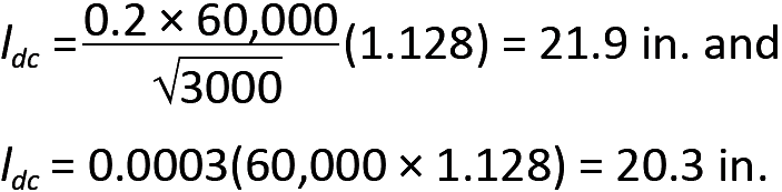
The bar diameter, db, is found in Appendix Table A-5.2. Using the larger value and rounding up, the minimum development length, ldc = 22 in. Because the tie spacing is greater than 4 in. on center, no reduction in development length may be taken.
3. Comparing the requirements for lap splice length and development length, the larger of the two values will be used: 25 in.
© 2020 Jonathan Ochshorn; all rights reserved. This section first posted November 15, 2020; last updated November 15, 2020.