
Contents | 1. Introduction to structural design | 2. Loads | 3. Wood |
Introduction to steel | Material properties | Sectional properties | Design approaches | Construction systems | Tension elements | Columns | Beams |
Steel structural elements are typically connected to each other using high-strength bolts or welds. Especially in so-called field connections — those that take place at the construction site — bolts are preferred, as they are easier, and generally less expensive, to execute in such contexts (outdoors, with unpredictable weather conditions, and without convenient access to welding equipment). Often, when welding is found to be either necessary or expedient, it occurs at the fabricating shop, although field welding is sometimes unavoidable.
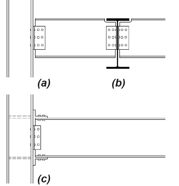
Steel connections are designated according to the types of forces and/or bending moments that are intended to be resisted, and that are symbolized by the hinges, rollers, or fixed constraints that populate load diagrams in statics texts (see Figure 1.14). In practice (see Figure 4.31), hinges and rollers become simple connections (previously designated as Type 2); fixed joints become fully restrained, or FR, connections (previously designated as Type 1); and the intermediate conditions between simple and fully restrained, become partially restrained, or PR, connections (previously designated as Type 3).
High-strength bolts typically used to connect steel elements are stronger than the bolts most often used to connect wood elements: the two most commonly specified bolts used in steel structures in the U.S. are designated Group A (including A325 bolts with an ultimate strength, Fu = 120 ksi) and Group B (including A490 bolts with Fu = 150 ksi). A third type of high-strength bolt, developed in Japan, has more recently been designated as Group C (including F3043 bolts with Fu = 200 ksi). In contrast, A307 bolts typically used in wood connections have an ultimate strength, Fu = 60 ksi. Bolts used to connect steel elements are stressed most commonly in shear, tension, or a combination of shear and tension, as illustrated in Figure 4.32.
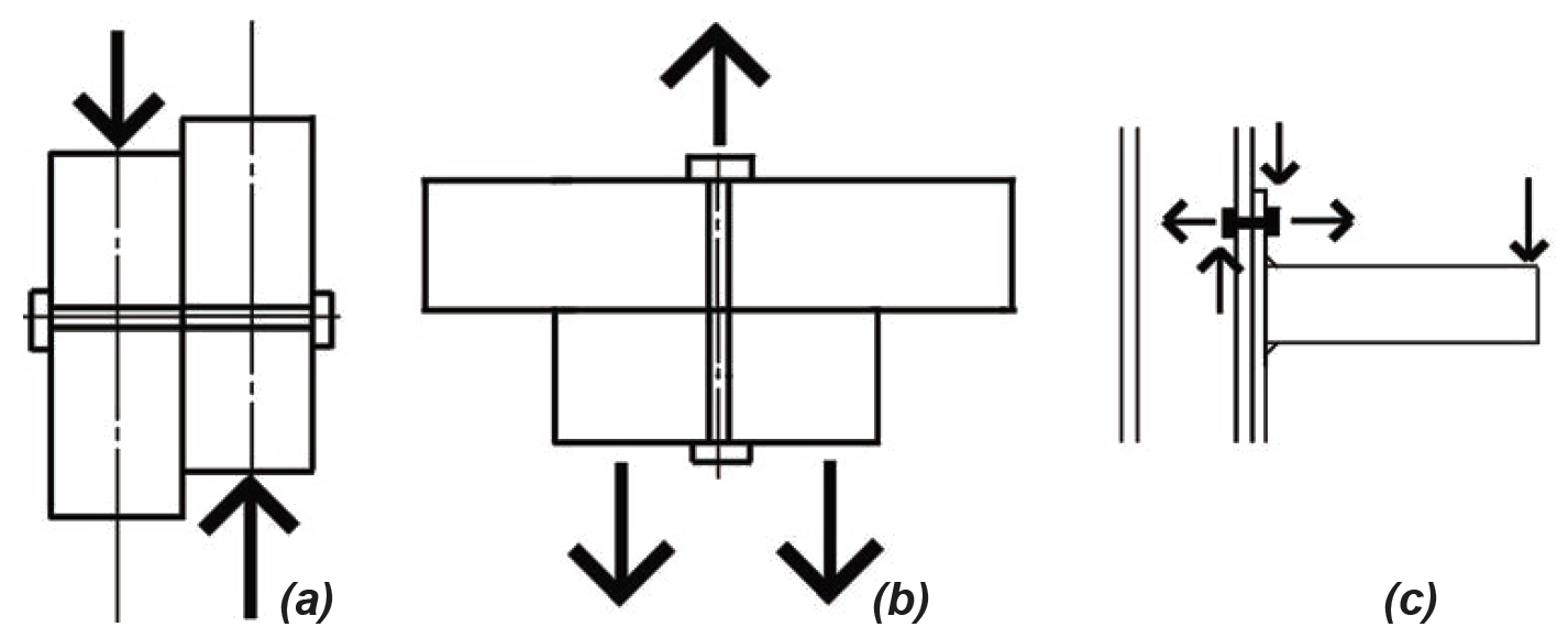
For shear connections, most bolts are designed so that they "bear" against the edge of the bolt holes into which they are inserted. These are bearing-type, or "snug-tightened" joints, and a small amount of slip of the bolt within the slightly-larger bolt hole is permitted. In the less common cases where no slip is desired — for example, in structures subjected to repeated stress reversals — so-called slip-critical connections are designed on the basis of the clamping force that the bolts place on the steel elements being joined, so that friction between the surfaces clamped together resists the tendency of the bolts to slip within the bolt holes. In either case (bearing or slip-critical bolt design), two separate strength criteria must be satisfied: (1) the shear strength of the bolt itself; and (2) the compressive capacity of the elements being joined, as the bolts "bear" on the inside surface of the bolt holes.
Shear capacity. The nominal bolt shear stress can be taken as 68 ksi for Group A (A325) bolts and 84 ksi for Group B (A490) bolts: when divided by the safety factor for bolt shear, Ω = 2.00, the allowable stresses become 34 ksi for Group A and 42 ksi for Group B bolts. These values assume that the threaded part of the bolt shaft does not penetrate as far as the actual shear planes (designated as condition X, for threads "eXcluded" from the shear planes); in cases where the threaded portions of the shaft penetrate, or are included within, the shear planes (condition N for "iNcluded"), these available strengths are reduced by 80% to 27 ksi for Group A bolts and 34 ksi for Group B bolts. The capacity of a single bolt in shear is found by multiplying the appropriate available stress by the nominal bolt area, and then by the number of shear planes in the connection (typically either one or two corresponding to single or double shear). Typical values for the available shear strength of bolts can be found in Appendix Table A-4.18. While these values no longer include an implicit allowance (factor of safety) to account for unequal force distribution or eccentricities that may occur when groups of bolts are subjected to shear, we will assume in the examples that follow that all bolts are stressed equally. In such cases, the shear capacity of the connection is the sum of the capacities of the individual bolts, that is, the single-bolt capacity times the number of bolts in the connection. Slip-critical bolts are given a lower nominal shear stress, effectively requiring more bolts per connection, thereby ensuring that no slip will occur.
Bearing capacity. The nominal bearing capacity of a bolt, Rn = 3.0dbtFu, depends on the strength of the material being bolted, measured by its minimum tensile strength, Fu, but may be reduced if the bolt holes are too closely spaced, or too close to the edge of the material being connected (when such clear spacing between bolt holes, or between a hole and the material edge, is less than 2 in., multiply Rn by Lc/2, where Lc is the smallest clear distance measured in the direction of the applied force). In this equation, db is the nominal bolt diameter and t is the thickness of the material upon which the bolt is bearing. The lowercase d in the abbreviation for bolt diameter, db, is consistent with steel industry practice, while the wood industry uses capital D to represent the diameter of nails and bolts (see Chapter 3). For bolts in single shear, the governing thickness is the thickness of the thinner element being joined. For bolts in double shear, the relevant thickness is either that of the middle piece, or the combined thicknesses of the two outer (side) pieces, whichever is less (assuming that all elements being joined are made from the same material). For connections made from different types of steel, bearing capacity should be computed for each element, based on its own thickness and material properties, with the smaller capacity governing the connection design for bearing.
Dividing the nominal bearing capacity by the safety factor for bearing, Ω = 2.0, we get the available strength for a bolt in bearing, Rn/Ω = 1.5dbtFu, multiplied by Lc/2 as before, where the clear bolt hole spacing (or distance to the edge) is less than 2 in. The available strength is reduced by 80% for cases where the small deformations associated with bolt bearing, at ordinary service loads, are considered to be a design issue. Typical values for the available bearing strength of bolts can be found in Appendix Table A-4.19. The bearing capacity of the connection is the sum of the capacities of the individual bolts, that is, the single-bolt capacity times the number of bolts in the connection. The bolt hole diameter (assuming standard holes) used in the calculation of bolt hole spacing can be taken as 1/16 in. greater (or 1/8 in. greater for bolts with diameters of 1 in. or larger) than the nominal bolt diameter, rather than increasing this bolt hole diameter by 1/16 in. as is required in the calculation of net area for steel tension elements. For example, the clear bolt hole spacing for 3/4-in.-diameter bolts spaced 3 in. on center in the direction of the force, Lc = 23/16 in., is found by subtracting the bolt hole diameter (3/4 + 1/16 = 13/16 in.) from the centerline spacing (3 in.).
Minimum and maximum spacing. Bolts that are used to connect steel elements are also subjected to minimum and maximum spacing rules. The basic suggested minimum centerline spacing between bolts is 3 times the nominal bolt diameter, db, although a spacing no greater than 22/3 times db is permitted. In either case, the clear distance between bolt holes cannot be less than db . The minimum centerline distance to any edge varies, depending on the bolt diameter. Minimum spacing and edge distance requirements are given in Appendix Table A-4.20 for typical bolt sizes. In addition to these minimum spacing requirements, bolts are also subjected to maximum spacing rules, with 12 in. being the maximum centerline bolt spacing, in the direction of the applied load, permitted for plates bolted to another element (for example, to another plate, or to a rolled section). Where either element being joined is less than 1/2 in. thick, this maximum spacing may be reduced to 24 times the thickness of the thinner element. Similarly, the maximum edge distance, measured from the bolt centerline, is 6 in., which may be reduced for elements less than 1/2 in. thick to 12 times the element thickness. These requirements can be found in Appendix Table A-4.20 part C, for typical member thicknesses.
Tension, shear and block shear. Where bolt holes reduce the cross-sectional area of a tension element, the design of the tension element itself must account for this reduced net, or effective net, area, as described previously for steel tension elements. For coped beams bolted to the webs of girders, block shear must be checked, as described previously for steel beams.
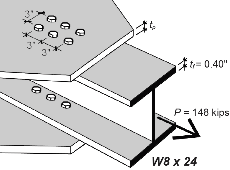
Problem definition. Examine the W8 × 24 wide-flange shape used as a tension element in a steel truss (the section's capacity was determined to be 148 kips in Example 4.1 when using two lines of 3/4 in. diameter bolts). Find the required number of bolts so that their available strength is no less than the beam's tension capacity (Figure 4.33). Assume A36 steel for the W8 × 24 section, and A490 high-strength bearing-type bolts (threads included in the shear plane).
Solution overview.. Find the required number of bolts based on bolt shear; check for bolt bearing.
Problem solution
1. Required number of bolts (design based on shear): From Appendix Table A-4.18 part A, for A490 bolts and 3/4 in. bolt diameter, the shear capacity per bolt is 18.6 kips, assuming threads excluded from the single shear plane. Based on Note 1 (for threads included in shear plane), this value is reduced by 80%, so the capacity per bolt becomes 0.80 × 18.6 = 14.88 kips per bolt. The required number of bolts is equal to the total capacity divided by the capacity per bolt, or 148/14.88 = 9.95 bolts. Clearly, this number must be rounded up to an integer that is divisible by 4, so that the four lines of bolts distributed on the two flanges all have the same number: therefore, we provisionally select 12 bolts, as shown in Figure 4.33.
1. Check required number of bolts (based on bearing capacity): From Appendix Table A-4.19, the bearing capacity per bolt, per inch of A36 material thickness, is 65.3 kips. As can be seen from Appendix Table A-4.3, the flange thickness of a W8 × 24 section is 0.40 in. Therefore, the capacity of a single bolt, based on bearing on the flange thickness, is 0.40 × 65.3 = 26.12 kips. The total capacity of the 12-bolt connection, again based on bearing, is 12 × 26.12 = 313 kips. Since this capacity is no smaller than the capacity determined in step 1 for shear, the provisional selection of 12 bolts is satisfactory. For a bearing capacity less than that determined for shear, the number of bolts would need to be increased accordingly, and the bolt design would be governed by bearing instead of shear.
Two pieces of steel may be welded together, not by directly melting one piece into the other, but rather by depositing melted steel contained in a separate electrode along the surfaces of the two steel pieces to be joined. Naturally, some melting of the joined pieces occurs as the "weld" steel is deposited; however, the weld and adjacent surfaces rapidly cool and harden as the electrode moves along the weld line, effectively connecting the pieces together. While there are numerous types of weld geometries — including groove welds, plug welds, and slot welds — the most common is the triangular fillet weld (pronounced fill-it). In what follows, we will discuss the strength of fillet welds subjected to loads parallel, perpendicular, or angled to the weld line.
As can be seen in Figure 4.34, a fillet weld is assumed to fail along the surface defined by its throat, labeled t in Figure 4.34a, whether the weld itself is stressed in tension, compression, or shear.
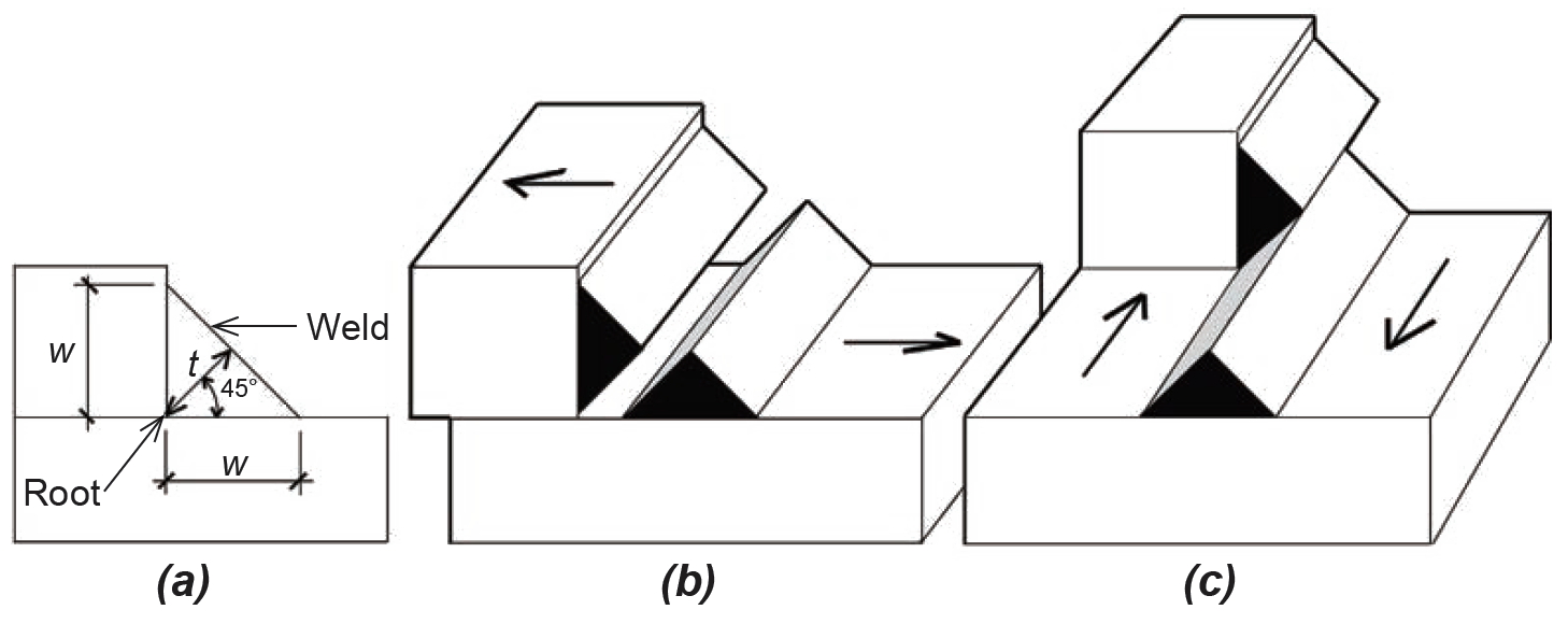
With symmetrical welds angled at 45° to the surfaces being joined, it can be seen that the throat dimension, t, equals 0.707w (where w is the hypotenuse of a 45° right triangle with both legs equal to t). For a weld of length, Lt, the surface area resisting either tension, compression, or shear is therefore Aw = tL = 0.707wL. A typical one-inch length of weld (that is, with L = 1), therefore has a failure surface area of Aw1 = 0.707w. The nominal strength (capacity) of a weld loaded "longitudinally" — that is, as shown in Figure 4.34c — is found by multiplying this surface area by the weld strength, taken as 0.6FEXX, where FEXX depends on the strength of the electrode used. For A36 (Fy = 36 ksi) and A992 (Fy = 50 ksi) steel, an electrode is typically specified with FEXX = 70 ksi, designated generically as E70XX. Putting this all together, we can compute the nominal strength of a 1-in.-long longitudinal weld: Rwl = 0.707(0.6 × 70)(w) = 29.69w kips per inch of weld length. The available strength is found by dividing this nominal capacity by the safety factor, Ω = 2.0, so that Rwl /Ω = 14.85w kips per inch of weld.
The general equation for all fillet welds, loaded longitudinally as shown in Figure 4.34c, transversely as shown in Figure 4.34b, or at any angle in between, is:
where
Rn/Ω = the available strength of a one-inch-long weld (kips).
θ = the angle (from 0° to 90°) between the weld line and the direction of load.
w = the weld size, or leg length (in.).
It can be seen that for longitudinal welds, with θ = 0°, the parenthetical term drops out, and Equation 4.15 is as derived earlier. For θ = 90° (a transverse weld), the capacity increases by a factor of (1.0 + 0.50 sin1.5 90°) = 1.5. The available strengths for longitudinal and transverse welds are therefore as follows: for a one-inch-long longitudinal weld, we get
while the available strength for a one-inch-long transverse weld is
In these equations, Rwl /Ω and Rwt /Ω are the available strengths (kips) of a one-inch-long weld oriented, respectively, longitudinally or transversely to the load, and w is the weld size, or leg length (in.). Where both longitudinal and transverse welds occur in the same connection, the available strength is taken as either (Rwl /Ω + Rwt /Ω) or (0.85Rwl /Ω + 1.5Rwt /Ω), whichever is greater. Other constraints on fillet weld design are discussed below. Weld size limits. Weld sizes cannot simply be determined on the basis of Equations 4.16 or 4.17 in order to satisfy the requirements for available strength of a connection. Rather, they are also constrained by the dimensions of the material welded together. Minimum weld sizes must be proportioned according to the thickness of the materials being joined; while maximum weld sizes must be no larger than the edge along which the weld is deposited or, where the edge is 1/4 in. or more thick, must be at least 1/16 in. smaller than any such edge (these size constraints are summarized in Appendix Table A-4.21). For this reason, it is more common to first establish a provisional weld size according to these minimum and maximum limits, and then determine the required total weld length. For connections with combinations of longitudinal and transverse welds, the design process is necessarily iterative, unless one of the weld lengths, either for the longitudinal or transverse portion, can be initially determined from the connection geometry.
The minimum length of a fillet weld is required to be at least four times its leg size. Otherwise the effective size of the weld, used in calculations, must be taken as no more than one-fourth of the weld length. For example, the minimum weld length for a 1/2 in. leg size is 4 × 1/2 = 2 in. If a 1/2 in. weld size is used with a shorter weld length — say 1 in. — the effective weld size used in calculating the available strength of the weld would be no more than the actual length (1 in.) divided by 4, or 1/4 in, even though the actual weld size is 1/2 in.
Longitudinal welds. For symmetrical and parallel longitudinal welds, the weld length, L, must be no smaller than the distance between the two weld lines, W, as shown in Figure 4.35.
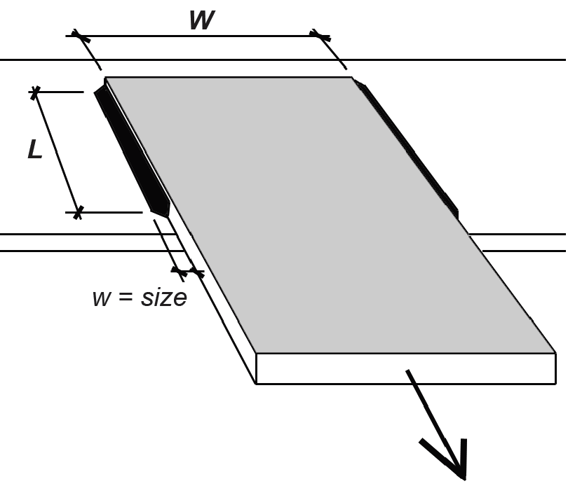
Where such welds transmit force to the "end" of an element subject to tension or compression (that is, through an "end-loaded" weld), an effective length Le = βL is used to compute the weld capacity, where β is defined as follows:
In other words, where the ratio of weld length to weld size, L/w ≤ 100, β = 1.0, and the effective length equals the actual weld length. Otherwise, β = 1.2 – 0.002(L/w), with a lower limit of β = 0.60 where the ratio of weld length to weld size, L/w ≥ 300.
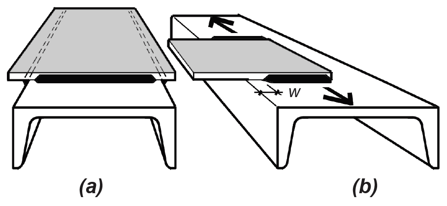
Fillet weld terminations. In certain cases, fillet welds should be terminated before reaching the edge of the steel elements they are connecting, to prevent damage (notching, gouging) of the element's edge. Figure 4.36a illustrates a condition where the fillet weld at the underside of a plate (shown as a dotted line) is interrupted at the corners before turning 90° and being deposited on the opposite side of the same plate. Figure 4.36b illustrates a lap joint that extends beyond a tension element: in such cases, it is accepted practice for the fillet weld to terminate a distance equal to the weld size, w, from the edge of the tension element.
Shear strength of connecting elements. Where welded connecting elements such as gussets, angles, or other plates are subjected to shear, the required thickness, t, of such elements can be found by equating the available shear strength of the connector, per unit length, to the available longitudinal weld strength, again per unit length. The available shear strength of the connector is 0.6Fut/Ω, while that of a single longitudinal weld, from Equation 4.16, is Rwl /Ω = 14.85w. For a connector welded on both sides of the plate, the available strength of the weld doubles to 2 × 14.85w = 29.69w. Equating these strengths using a safety factor, Ω = 2.00 and a tensile strength, Fu = 58 ksi (corresponding to a connector fabricated from A36 steel), we get the following required connector thickness, tmin (in.) for a given weld size, w (in.), where the connector plate is welded on both sides:
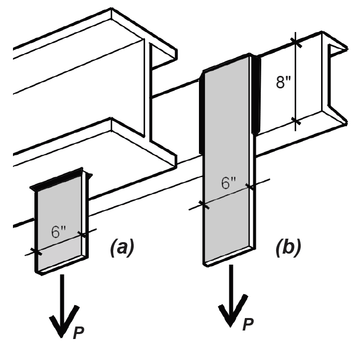
Problem definition. Find the capacities of the 6-in.-wide, 7/8-in.-thick plates shown in Figure 4.37, welded to (a) a wide-flange shape with transverse welds, and (b) an 8-in.-deep channel shape with longitudinal welds. In each case, assume that the plates are fabricated from A36 steel, and that the weld size is 3/8 in. Use an E70XX electrode with Fu = 70 ksi.
Solution overview.. Find the capacity of the welds; confirm that the tensile capacity of the plates is no smaller than the weld capacity.
Problem solution
1. Based on Equations 4.16 and 4.17, we can express the capacity of the transverse and longitudinal welds as follows:
For the transverse weld, the unit capacity, Rwt /Ω = 1.5(14.85w) = 1.5(14.85)(3/8) = 8.35 kips per inch of weld. There is a total of 6 × 2 = 12 in. of transverse weld on the two plates (since the plate width, W = 6 in.), so the total capacity for the transverse welds, Pt = 8.35(12) = 100.2 kips.
For the longitudinal weld, the unit capacity, Rwl /Ω = 14.85w = 14.85(3/8) = 5.57 kips per inch of weld. Since this is an "end-loaded" condition, the ratio of weld length to weld size must be checked: L/w = 8/(3/8) = 21.3 is no greater than 100, so the effective weld length equals the actual length, which is 8 in. There is a total of 8 × 2 = 16 in. of longitudinal weld on the plate, so the total capacity for the longitudinal welds, Pl = 5.57(16) = 89.1 kips. The weld length, L = 8 in. cannot be smaller than the distance between the two weld lines, in this case equal to the plate width of 6 in.
2. The tensile capacity of both plates is based on the smaller of the following: either the capacity to resist tensile yielding on the gross area or to resist rupture on the net area. The capacity based on yielding (see previous section in this chapter) is 0.6FyAg = 0.6(36)(7/8 × 6) = 113.4 kips. The capacity based on rupture is 0.5FuAn = 0.5(58)(7/8 × 6) = 152.2 kips. The governing tensile capacity, 113.4 kips, is larger than the actual capacity of either weld condition, so the strength of the welds governs both designs. For short gusset plates, the effective net area is taken as equal to the net area, so long as it is no bigger than 85% of the gross area.
3. Conclusion: the capacity of Plate a, Pt , equals 100.2 kips; and the capacity of Plate b, Pl , equals 89.1 kips.
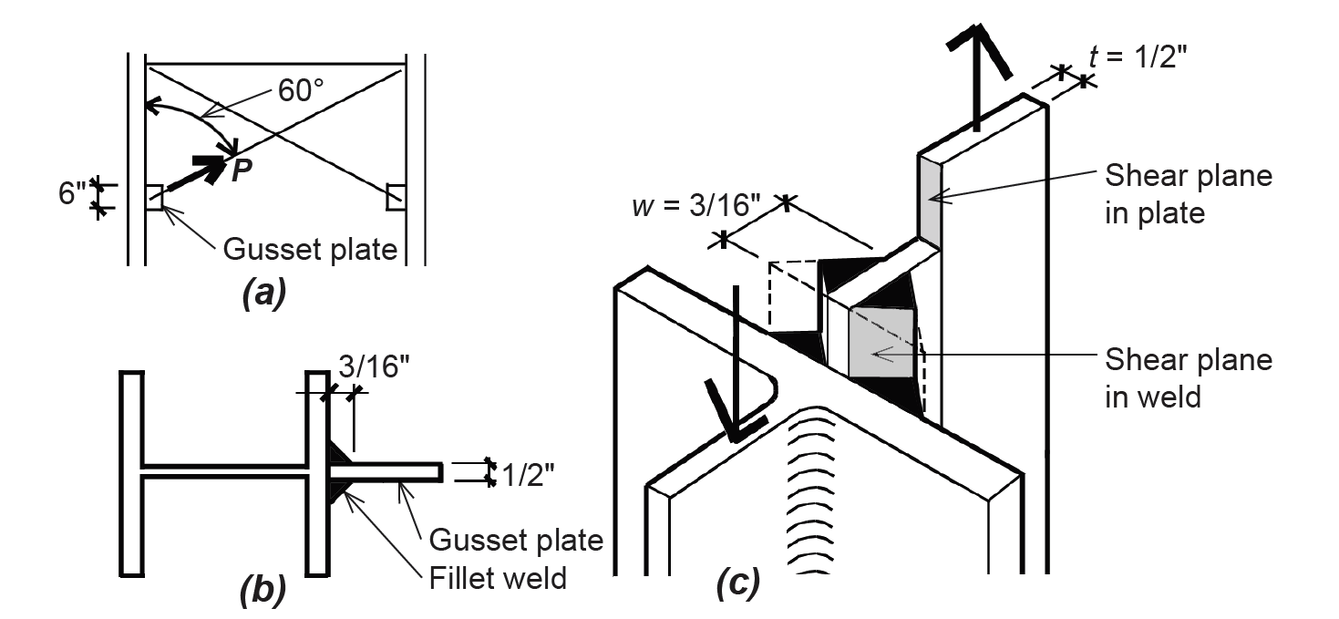
Problem definition. Find the capacity of the 1/2-in.-thick plate shown in Figure 4.38, welded to a wide-flange column shape. Assume that the plate is fabricated from A36 steel, and that the weld size is 3/16 in., on both sides of the plate. Use an E70XX electrode with Fu = 70 ksi.
Solution overview.. Confirm that the shear capacity of the plate is greater than the capacity of the weld; compute the available strength of the weld.
Problem solution
1. From Equation 4.19, the required thickness of the plate (that is, the plate thickness consistent with the maximum available shear strength of a weld on both sides of a connector plate) is tmin = 1.71w = 1.71(3/16) = 0.32 in. In this calculation, we have compared the weld and plate shear strength as if the load were parallel to the weld, even though the actual load on the connector is oriented at a 60° angle to the weld line.
2. Since the actual plate thickness of 1/2 in. is larger than the required thickness, tmin = 0.32 in., the weld will fail in shear before the plate does. For this reason, we can find the capacity (available strength) of the connector by determining the available strength of the weld, per inch of length, according to Equation 4.15: Rn/Ω = 14.85w(1.0 + 0.50 sin1.5 θ) = 14.85(3/16)(1.0 + 0.50 sin1.5 60) = 3.91 kips per inch of weld.
3. The total weld length is 6 × 2 = 12 in., so the total available strength of the connector, P = 12(3.91) = 46.9 kips.
Problem definition. Find the required longitudinal weld length, L, on the two 1/2-in.-thick plates shown in Figure 4.39, to resist a load, P = 80 kips. Assume that the plate is fabricated from A36 steel. Use an E70XX electrode with Fu = 70 ksi.
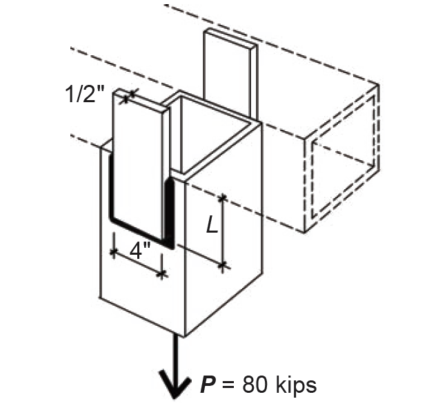
Solution overview.. Confirm that capacity of both plates is no less than 80 kips; find the required longitudinal weld length so that the total weld capacity is no less than 80 kips.
Problem solution
1. The tensile capacity of both plates is based on the smaller of the following: either the capacity to resist tensile yielding on the gross area or to resist rupture on the net area. The capacity based on yielding (see previous section in this chapter) is 0.6FyAg = 0.6(36)(1/2 × 4 × 2) = 86.4 kips. The capacity based on rupture is 0.5FuAn = 0.5(58)(1/2 × 4 × 2) = 116 kips. The governing tensile capacity, 86.4 kips, is larger than the actual load of 80 kips, so the plates are satisfactory. For short gusset plates, the effective net area is taken as equal to the net area, so long as it is no bigger than 85% of the gross area.
2. From Appendix Table A-4.21, for a 1/2-in.- thick plate, the minimum weld size is 3/16 in., and the maximum weld size is 1/2 – 1/16 = 7/16 in. For this example, we will choose a weld size of w = 3/16 in.
3. Based on Equations 4.16 and 4.17, we can express the capacity of the longitudinal and transverse welds as follows:
For the longitudinal weld, the unit capacity, Rwl /Ω = 14.85w = 14.85(3/16) = 2.784 kips per inch of weld. There is a total of 4L in. of longitudinal weld on the two plates (where L is the length of each longitudinal segment), so the total capacity for the longitudinal welds, Pl = 2.784(4L) = 11.138L kips.
For the transverse weld, the unit capacity, Rwt /Ω = 1.5(14.85w) = 1.5(14.85)(3/16) = 4.177 kips per inch of weld. There is a total of 4 × 2 = 8 in. of transverse weld on the two plates (since the plate width, W = 4 in.), so the total capacity for the transverse welds, Pt = 4.177(8) = 33.413 kips.
4. Where both longitudinal and transverse welds occur in the same connection, the available strength is taken as either (a) Rwl /Ω + Rwt /Ω; or (b) 0.85Rwl /Ω + 1.5Rwt /Ω, whichever is greater. The terms Rwl /Ω and Rwt /Ω refer to the available strengths (capacities) of the longitudinal and transverse welds, respectively; therefore, we must test both alternatives, setting the capacities equal to the load, P = 80 kips and solving for the required length, L:
Rwl /Ω + Rwt /Ω = 11.138L + 33.413 = 80; from which L = 4.18 in.
0.85Rwl /Ω + 1.5Rwt /Ω = 0.85(11.138L) + 1.5(33.413) = 80; from which L = 3.16 in.
5. Since the greater capacity of the two alternatives may be used, the smaller length, L = 3.16 in. is acceptable. Looked at another way, if the length for both alternatives were set at L = 3.16 in., case (a) would have a capacity smaller than 80 kips, while case (b) would have a capacity exactly equal to 80 kips; it can be seen that case (b) has the greater capacity and therefore would govern the design. Increasing the length to 4.18 in. found in case (a) is not required. We round up the required length for the longitudinal weld to 3-1/2 in.
© 2020 Jonathan Ochshorn; all rights reserved. This section first posted November 15, 2020; last updated November 15, 2020.