
Contents | 1. Introduction to structural design | 2. Loads | 3. Wood |
Introduction to steel | Material properties | Sectional properties | Design approaches | Construction systems |
Unlike tension elements designed in timber, two modes of failure are considered when designing tension members in steel. First, the element might become functionally useless if yielding occurs across its gross area, at the yield stress, Fy . Since internal tensile forces are generally uniform throughout the entire length of the element, yielding would result in extremely large deformations. On the other hand, if yielding commenced on the net area (where bolt holes reduce the gross area), the part of the element subjected to yield strains would be limited to the local area around the bolts, and excessive deformations would not occur. However, a second mode of failure might occur at these bolt holes: rupture of the element could occur if, after yielding, the stresses across the net area reached the ultimate stress, Fu. As in wood design, typical bolt hole diameters are 1/16 in. larger than the actual bolt diameter (except that for bolts with diameters greater or equal to 1 in., the bolt hole diameter is made 1/8 in. larger). However, because a small amount of material surrounding the bolt hole is damaged as the hole is punched, an additional 1/16 in. is added to the hole diameter for the purpose of calculating net area, resulting in a bolt hole diameter taken as 1/8 in. larger than the nominal bolt diameter for steel elements (or 3/16 in. larger for bolts with diameters of 1 in. or larger).
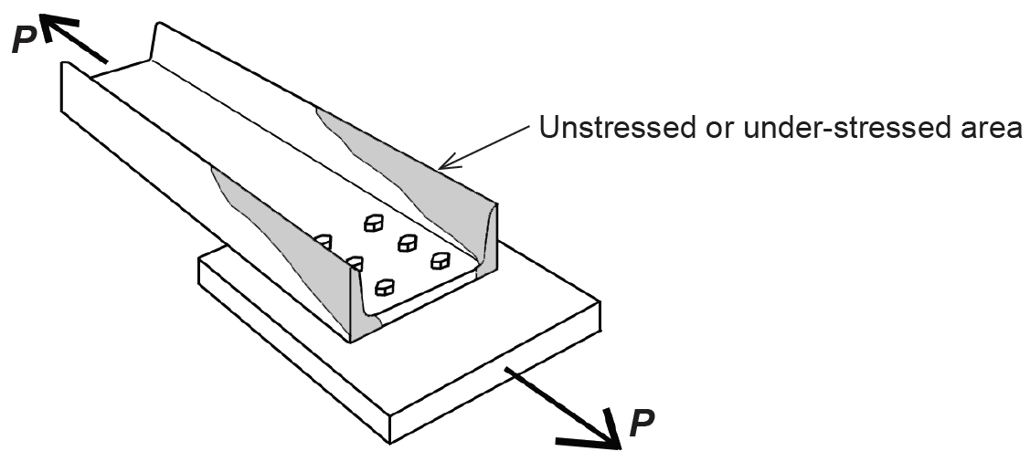
Another difference in the design of wood and steel tension elements occurs because nonrectangular cross sections are often used in steel. If connections are made through only certain parts of the cross section, as illustrated in Figure 4.11, the net area in the vicinity of the connection will be effectively reduced, depending on the geometry of the elements being joined, and the number of bolts being used. This effective net area, Ae, is obtained by multiplying the net area, An, by a coefficient, U, defined in Appendix Table A-4.9.
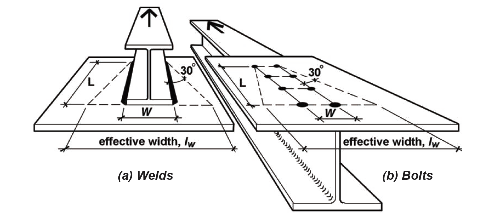
Where all parts (i.e., flanges, webs, etc.) of a cross section are connected, and the so-called shear lag effect described above cannot occur, the coefficient U is taken as 1.0, and the effective net area equals the net area, just as in timber design. For short connection fittings like splice plates and gusset plates, U is also taken as 1.0, but Ae = An cannot exceed 0.85 times the gross area. These short connecting elements may have an effective width less than their actual width to account for the shear lag effect, based on what is known as the "Whitmore section," shown in Figure 4.12. For a length, L, of the fastener group measured in the direction of load, and a distance, W, between the outer rows of bolts or welds, the effective width is computed by extending a 30° line out from both sides of the fastener group; it can be seen that the effective width, lw, is equal to 2Ltan30° + W.
Finally, the lengths of tension members, other than rods and cables, are recommended, but not required to have, a slenderness ratio — defined as the ratio of effective length to least radius of gyration
— of 300, to prevent excessive vibrations and protect against damage during transportation and erection. The radius of gyration, a property of the cross section, is equal to ![]() , where I is the moment of inertia and A is the cross-sectional area of the element.
, where I is the moment of inertia and A is the cross-sectional area of the element.
From the preceding discussion, it can be seen that two values for available strength, or allowable stress, in tension need to be determined: one for yielding of the gross area and one for failure (rupture) of the effective net area. These two values are:
and
where Ftgross and Ftnet are the allowable tensile stresses for steel corresponding to the two modes of failure, or limit states: Fy is the yield stress and Fu is the ultimate stress for steel (Appendix Table A-4.1). The tensile stress is computed on the gross area in the same manner as for wood (see Equation 3.2). Rupture on a failure surface through bolted or welded connections, however, is determined using the effective net area rather than the net area, so Equation 3.3 (for wood) must be modified for steel connections as follows:
When computing the capacity based on yielding, the full gross area is available to resist the internal forces:
When computing the capacity on the effective net area:
The "available strength" limit states listed in Appendix Table A-4.2 are equivalent to these formulations based on allowable stress.
The following example illustrates the application of these principles to a steel tension problem. Different procedures are used for cables, eyebars, threaded rods, and pin-connected plates.
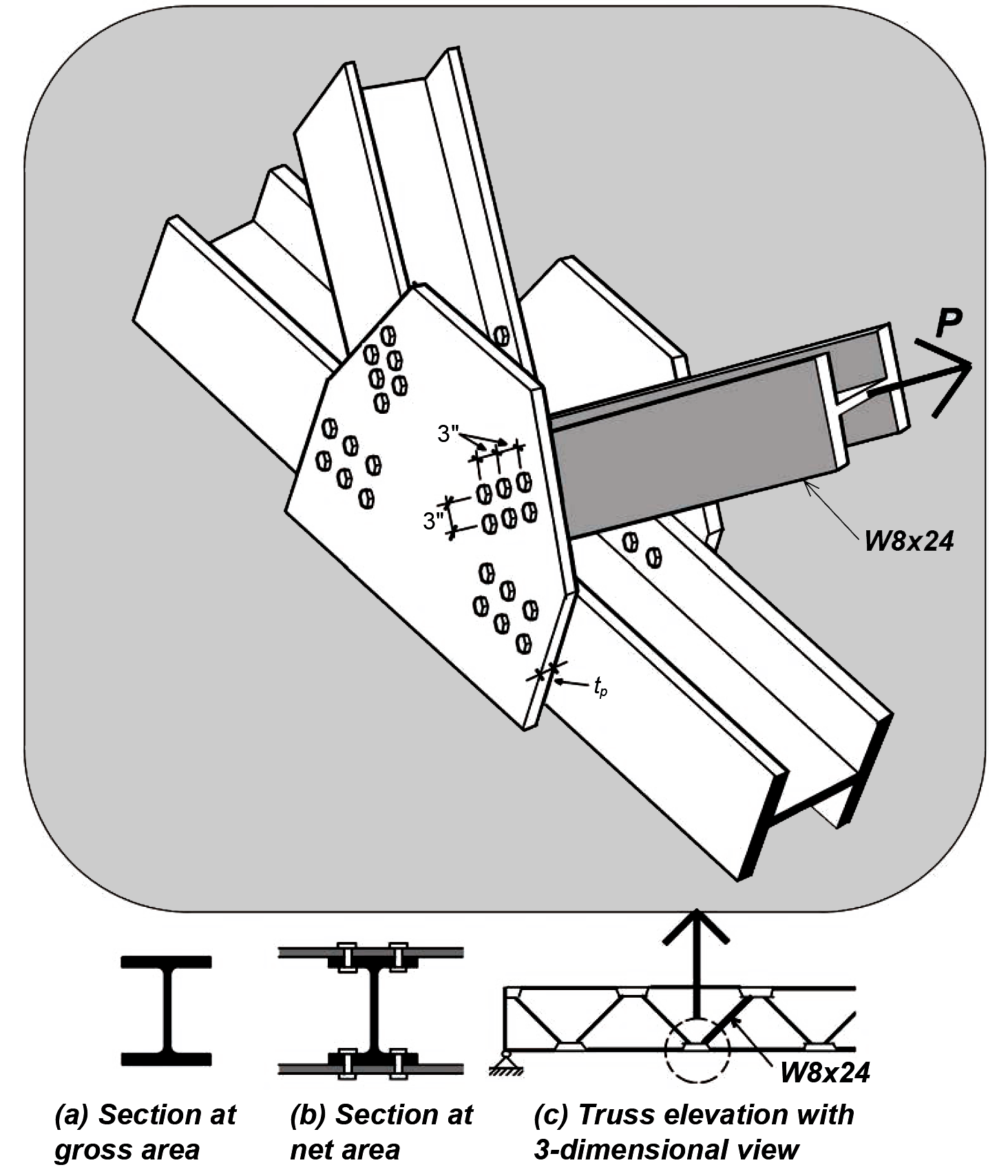
Problem definition. Find the maximum tension load, P, that can be applied to a W8 × 24 element connected to gusset plates within a truss with 3/4-in.-diameter bolts, as shown in Figure 4.13. Use A36 steel. Find the required thickness of the gusset plates so that their capacity is no smaller than that of the W8 × 24 tension element. The bolt hole diameter = bolt diameter + 1/8 in. = 7/8 in. = 0.875 in.
Solution overview. Find cross-sectional dimensions and material properties; find gross area capacity; find effective net area capacity; the governing capacity is the lower of these two values. For gusset plate thickness, find effective width based on Whitmore section; apply equations for gross and net area capacity to determine required plate thickness.
Problem solution
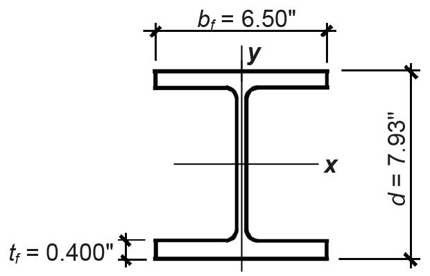
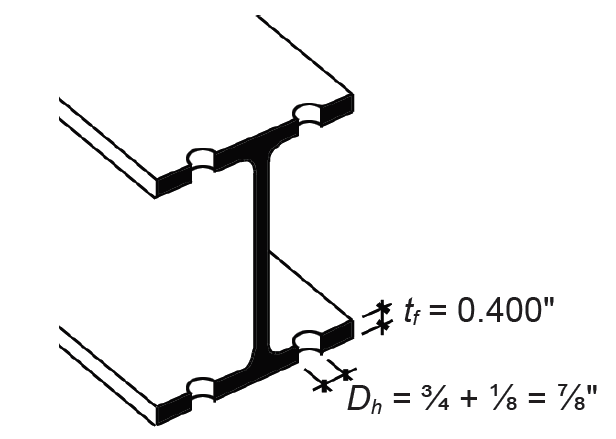
1. From Appendix Table A-4.3, find cross-sectional dimensions (Figure 4.14):
Ag = 7.08 in2
d = 7.93 in.
bf = 6.50 in.
tf = 0.400 in.
2. From Appendix Table A-4.1, find Fy = 36 ksi and Fu = 58 ksi.
3. Gross area: find capacity, P:
a. Using Equation 4.1 (or Appendix Table A-4.2) find Ftgross = 0.6Fy = 0.6(36) = 22 ksi.
b. Using Equation 4.4, P = Ftgross × Ag = 22(7.08) = 156 kips.
4. Effective net area: find capacity, P:
a. From Appendix Table A-4.9, find the shear lag coefficient, U:
U = 0.90 since the following criteria are met:
b. Find the net area, An (same as Equation 3.1 for wood). As shown in Figure 4.15:
An = Ag – (number of holes)(dh × t) = 7.08 – 4(0.875 × 0.400) = 5.68 in2.
c. Ae = U(An) = 0.9(5.68) = 5.11 in2.
d. Using Equation 4.2, find Ftnet = 0.5Fu = 0.5(58) = 29 ksi.
e. Using Equation 4.5, find P = Ftnet × Ae = 29(5.11) = 148 kips.
5. Conclusion: failure on the effective net area governs since 148 kips < 156 kips. The capacity (allowable load) is 148 kips.
6. We now can determine the thickness of the gusset plate, stressed in tension, with two lines of bolt holes per plate, using the Whitmore section to determine the effective width of the plate. As can be seen in Figure 4.12, the effective width, lw = 2(6)(tan 30°) + 3 = 9.9 in. The tensile capacity of the gusset plates may be based on either yielding of the gross area or rupture of the net area. First, the capacity based on yielding of the gross area of both plates is FtAg = 0.6(36)(2)(9.9tp) = 428tp kips. Next, the effective net area Ae = (2)(9.9 – 2 × 7/8)tp = 16.3tp in2, which cannot exceed 85% of the gross area for small gusset plates; i.e., it must be no larger than 0.85(2)(9.9tp) = 16.8tp in2. Therefore, the capacity based on rupture is 0.5(58)(16.3tp) = 473tp. Yielding governs, so the required thickness of the plate can be found by setting the required tensile capacity, 428tp equal to the governing load of 148 kips, from which tp = 0.35 in. Rounding up, we select a 3/8-in. thick gusset plate with tp = 0.375 in.
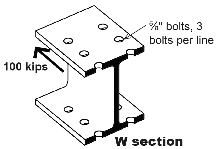
Problem definition. Select a W section bolted as shown in Figure 4.16 with 5/8 in. diameter bolts, and 3 bolts per line, to resist a tension force of 100 kips. Assume A36 steel. The effective bolt hole diameter = bolt diameter + 1/8 in. = 5/8 + 1/8 = 3/4 in. = 0.75 in.
Solution overview. Find the required area based on net area capacity, assuming values for shear lag coefficient, U, and flange thickness, tf ; find required area based on gross area capacity; use the larger of the two area values to provisionally select a W section; check using "analysis" method if either U is smaller or tf is larger than assumed values. The area of the selected W section can be somewhat smaller than the "required" area if either U is larger or tf is smaller than assumed values — check using "analysis" method.
Problem solution
1. Gross area: find required gross area based on yielding. From Equation 4.4, the required gross area, Ag = P/Ftgross = 100/(0.6 × 36) = 4.63 in2.
2. Effective net area: find required gross area after determining effective net area based on rupture through failure surface (assume U = 0.9 and tf = 0.4 in.):
a. From Equation 4.5, the required effective net area, Ae = P/Ftnet = 100/(0.5 × 58) = 3.45 in2.
b. Working backwards, the required net area, An = Ae/U = 3.45/0.9 = 3.83 in2.
c. Finally, the required gross area can be computed: Ag = An + (bolt hole area) = 3.83 + 4(0.75 × 0.4) = 5.03 in2.
3. Since 5.03 in2 > 4.63 in2, the calculation based on effective net area governs, and a W section must be selected with Ag ≥ 5.03 in2. Many wide-flange shapes could be selected. From Appendix Table A-4.3, the following candidates are among those that could be considered:
a. Check a W8 × 18 with Ag = 5.26 in2. Two assumptions need to be tested: that U = 0.9, and that tf ≤ 0.4 in. From Appendix Table A-4.3, bf = 5.25 in., d = 8.14 in. and tf = 0.330 in. From Appendix Table A-4.9, the criteria for U = 0.9 requires that bf = 5.25 ≥ 0.67d = 0.67(8.14) = 5.45 in. Since this condition is not met, we must use U = 0.85. Additionally, the flange thickness is different from our assumed value of 0.40 in., so that the calculation of net and effective area will change: An = Ag – (bolt hole area) = 5.26 – 4(0.75 × 0.330) = 4.27 in2 and Ae = U × An = 0.85(4.27) = 3.63 in2. The capacity based on rupture through the effective net area is P = Ftnet × Ae = (0.5 × 58)(3.63) = 105 k. The capacity based on yielding on the gross area has already been found satisfactory (since the gross area of the W8 × 18 is greater or equal to the required gross area computed above). Therefore, the W8 × 18 is acceptable.
b. Check a W6 × 20 with Ag = 5.87 in2. The same two assumptions need to be tested: that U = 0.9, and that tf ≤ 0.4. From Appendix Table A-4.3, bf = 6.02 in., d = 6.20 in. and tf = 0.365 in. From Appendix Table A-4.9, the criteria for U = 0.9 requires that bf = 6.02 ≥ 0.67d = 0.67(6.20) = 4.15 in. Since this condition is met, and since its net area is greater than assumed (this is so because its flange thickness, tf , is less that the value assumed, so that the bolt hole area is less than assumed, and therefore the net area is greater than assumed), the W6 × 20 is acceptable.
Both the W8 ×18 and the W6 × 20 would work, as would many other wide-flange shapes. Of the two sections considered, the W8 × 18 is lighter (based on the second number in the W-designation that refers to beam weight in pounds per linear foot), and therefore would be less expensive.
Threaded rods are designed using an allowable tensile stress, Ft = 0.375Fu , which is assumed to be resisted by the gross area of the unthreaded part of the rod. This value for the allowable stress is found by dividing the nominal rod tensile strength of 0.75Fu by a safety factor, Ω = 2.00. While there are no limits on slenderness, diameters are normally at least 1/500 of the length, and the minimum diameter rod for structural applications is usually set at 5/8 in. Assuming A36 steel, with Fu = 58 ksi (Appendix Table A-4.1), the smallest acceptable rod with area, A = π(5/16)2 can support a tensile load, P = Ft × A = 0.375Fu × π(5/16)2 = 21.75 × 0.3068 = 6.67 kips.
Where plates are connected with a single pin, as shown in Figure 4.17, the net area, An, is defined, not by the length, b, on either side of the pin hole, but rather by an effective length, be = 2t + 0.63 ≤ b, where t is the thickness of the plate (Figure 4.17b):
The plate capacity in tension is governed by either yielding on the gross area or rupture on the net area, whichever is smaller (there is no effective net area in this case), with Pgross = 0.6Fy × Ag and Pnet = 0.5Fu × An as before. It is possible to cut the plate at a 45° angle as shown in Figure 4.17, as long as length c is greater or equal to length a, which in turn must be greater or equal to 1.33be.
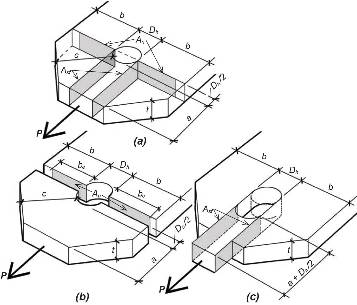
Aside from failure in tensile rupture or yielding, a third limit state for pin-connected plates is shear failure, or the relative sliding of areas Asf as illustrated in Figure 4.17c. In this case, the allowable shear stress is taken as 0.3Fu so that Pshear = 0.3Fu × Asf.
A fourth limit state for pin-connected plates is bearing, or compressive stress caused by the pin itself in direct contact with the adjacent plate. Here, the allowable stress on the projected area (Apb) of the pin that bears on the plate is 0.9Fy so that the allowable bearing strength is 0.9FyApb.
All four limit states must be checked, with the capacity of the pin-connected plate determined by the lowest of the four limits. Values for yield and ultimate stress used in these calculations, Fy and Fu , are listed in Appendix Table A-4.1.
For such pin-connected plates, as well as for all other bolted connections, the fasteners themselves, and not only the stresses they produce on the elements being joined, must also be checked. This aspect of structural element design is discussed more thoroughly in the section of this chapter dealing with steel connections.
© 2020 Jonathan Ochshorn; all rights reserved. This section first posted November 15, 2020; last updated November 15, 2020.