
Contents | 1. Introduction to structural design | 2. Loads | 3. Wood |
Introduction to steel | Material properties |
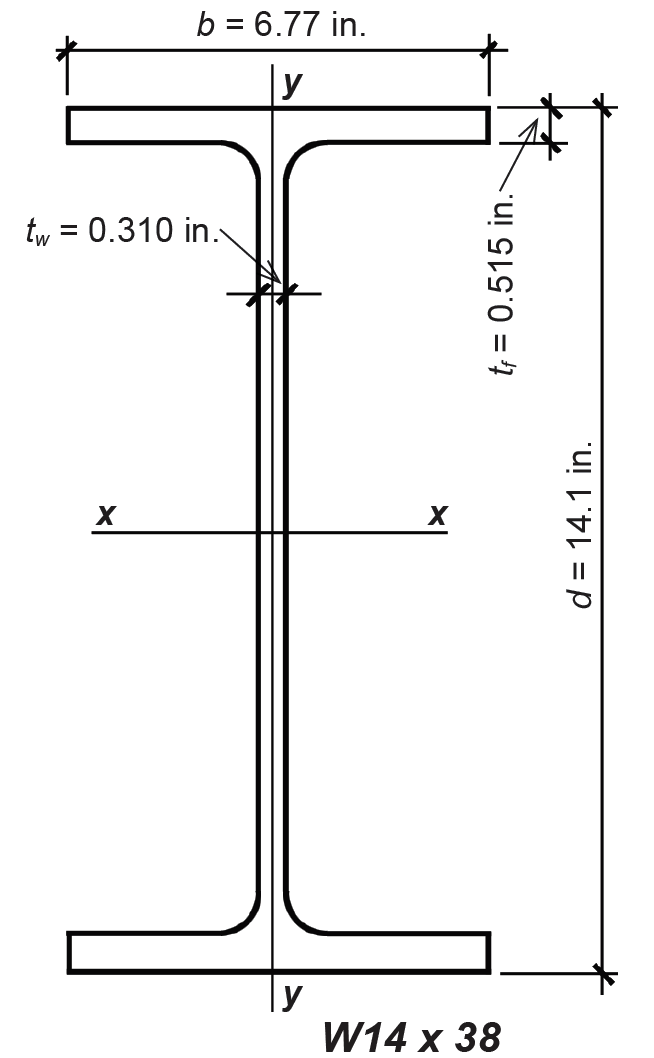
Wide-flange shapes are commonly used for both beams and columns within steel-framed structures. They are designated by a capital W, followed by the cross section's nominal depth (in.) and weight per linear foot (lb). For example, a W14 × 38 has a nominal depth of 14 in. and weighs 38 lb per linear foot (see Figure 4.3).
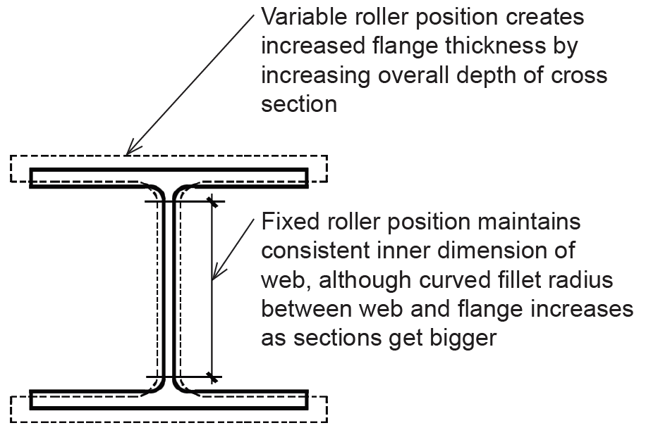
Unlike standard "I-beam" (S) sections, whose flange surfaces are not parallel — the inner surface slopes about 16% relative to the outer surface — wide-flange (W) sections have parallel flange surfaces, making it somewhat easier to make connections to other structural elements. Wide-flange sections are manufactured in groups with a common set of inner rollers. Within each of these groups, the dimensions and properties are varied by increasing the overall depth of the section (thereby increasing the flange thickness) and letting the web thickness increase as well. For this reason, actual depths may differ considerably from the nominal depths given to each group of shapes. On the other hand, traditional standard I-beam (S) sections are still manufactured with fixed outer rollers and variable inner rollers, so that actual depths are fixed for each group, and can therefore be configured with exact integer dimensions ranging from 3 to 24 inches (whereas wide-flange nominal depths range from 4 to 44 inches). A schematic illustration of roller positions for wide-flange shapes within a group is shown in Figure 4.4.
Dimensions of commonly available W shapes are listed in Appendix Table A-4.3. Other shapes, such as channels (C or MC), angles (L), pipes, and hollow structural sections (HSS) also have many structural applications; standard dimensions for some of these shapes are listed in Appendix Tables A-4.4 through A-4.8. The designation for channels (C and MC) follows that for wide-flange sections, with the nominal depth in inches followed by the weight in pounds per linear foot. For angles, three numbers are given after the symbol, L: the first two are the overall lengths of the two legs; the third is the leg thickness (always the same for both legs). Hollow structural sections (HSS) are designated with either two or three numbers corresponding to the diameter and nominal thickness (for round sections), or the two outside dimensions and nominal thickness (for rectangular sections). Steel pipe, similar in shape to round HSS, is designated by nominal outside diameter in three "weights": standard, extra strong, and double-extra strong.
© 2020 Jonathan Ochshorn; all rights reserved. This section first posted November 15, 2020; last updated November 15, 2020.