Jonathan Ochshorn
© 2009 Jonathan Ochshorn.
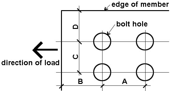
Directions: Enter values for bolt type (A325 or A490); bolt diameter; whether threads are included (N) or excluded (X) from the shear planes; the number of bolts in the connection; whether the connection is designed as "slip-critical"; the number of shear planes (single or double) in the connection; the material being connected (one grade of steel only for all members); the smallest effective plate thickness for bearing (for single shear connections, this is the thickness of the thinner member being connected; for double shear connections, this is the thinner of either the center member or the combined thicknesses of the outer members); whether small deformations associated with bearing stress are considered to be a design issue (yes or no); and various spacing and edge distance values (these can be excluded from the calculations if only a preliminary capacity is desired, with spacing and edge distances assumed to be consistent with maximum bolt capacity). Only the capacity based on the bolts themselves is computed: this calculator does not check the steel plates being connected for strength or serviceability.
Note that the minimum thickness of a single member (in the "Bolt spacing and edge distance" section) may differ from the minimum plate thickness (in the "Capacity in bearing" section). As explained above, the latter value combines the thicknesses of outer members in a double-shear connection; whereas the former value is based on the single thinnest member dimension.
For "slip critical" connections, it is permitted to choose "slip as a serviceability limit-state" for standard bolt holes.
Press "update" button.
This calculator assumes standard bolt holes, with members stressed only in shear (i.e., with no tension resisted by the bolts). Bolt capacity is based on the smaller of bolt shear and material bearing capacities, and, if desired, is adjusted based on bolt spacing (i.e., reductions in capacity are possible when bolt spacing is less than optimal).
More detailed explanations and examples can be found in my text.
Disclaimer: This calculator is not intended to be used for the design of actual structures, but only for schematic (preliminary) understanding of structural design principles. For the design of an actual structure, a competent professional should be consulted.
First posted October 8, 2009 | Last updated October 8, 2009