
Contents | 1. Introduction to structural design | 2. Loads |
Introduction to wood | Material properties | Sectional properties | Design approaches | Construction systems | Tension elements | Columns | Beams | Connections |
Table A-3.1: Design values for tension, Ft (psi) for visually graded lumber and glued-laminated timber
| A. Dimension lumber (2 in. – 4 in. thick) | |||||
|---|---|---|---|---|---|
| Species | Select Structural | No. 1 | No. 2 | No. 3 | Miscellaneous |
| Douglas Fir-Larch | 1000 | 675 | 575 | 325 | 1800 |
| Douglas Fir-Larch (North) | 825 | n/a | n/a | 300 | 2500 |
| Douglas Fir-South | 900 | 600 | 525 | 300 | |
| Hem-Fir | 925 | 625 | 525 | 300 | 1725 |
| Hem-Fir (North) | 775 | n/a | n/a | 325 | 2575 |
| Spruce-Pine-Fir | 700 | n/a | n/a | 250 | 2450 |
| Spruce-Pine-Fir (South) | 575 | 400 | 350 | 200 | |
| Southern Pine3 | 1000 | 650 | 525 | 300 | |
| B. Beams and stringers4 | |||||
|---|---|---|---|---|---|
| Species | Select Structural | No. 1 | No. 2 | No. 3 | Miscellaneous |
| Douglas Fir-Larch | 950 | 675 | 425 | n/a | |
| Douglas Fir-Larch (North) | 950 | 675 | 425 | n/a | |
| Douglas Fir-South | 900 | 625 | 425 | n/a | |
| Hem-Fir | 750 | 525 | 350 | n/a | |
| Hem-Fir (North) | 725 | 500 | 325 | n/a | |
| Spruce-Pine-Fir | 650 | 450 | 300 | n/a | |
| Spruce-Pine-Fir (South) | 625 | 450 | 300 | n/a | |
| Southern Pine5 | 1000 | 900 | 550 | n/a | |
| C. Posts and timbers6 | |||||
|---|---|---|---|---|---|
| Species | Select Structural | No. 1 | No. 2 | No. 3 | Miscellaneous |
| Douglas Fir-Larch | 1000 | 825 | 475 | n/a | |
| Douglas Fir-Larch (North) | 1000 | 825 | 475 | n/a | |
| Douglas Fir-South | 950 | 775 | 450 | n/a | |
| Hem-Fir | 800 | 650 | 375 | n/a | |
| Hem-Fir (North) | 775 | 625 | 375 | n/a | |
| Spruce-Pine-Fir | 700 | 550 | 325 | n/a | |
| Spruce-Pine-Fir (South) | 675 | 550 | 325 | n/a | |
| Southern Pine5 | 1000 | 900 | 550 | n/a | |
| D. Glued-laminated softwood timber | ||||
|---|---|---|---|---|
| Species | Grade (and Identification No.) | |||
| Douglas Fir-Larch (DF) | L3 (ID#1) 950 |
L2 (ID#2) 1250 |
L2D (ID#3) 1450 |
L1D L1 (ID#5) 1650 |
| Softwood Species (SW) | L3 (ID#22) 525 | Alaska Cedar (AC) | L3 (ID#69) 725 |
L2 (ID#70) 975 |
L1D (ID#71) 1250 |
L1S (ID#72) 1250 |
Southern Pine (SP) | N2M14 N2M12 (ID#47) 1200 |
N2D14 N2D12 (ID#48) 1400 |
N1M16 (ID#49) 1350 |
N1D14 (ID#50) 1550 |
Notes:
1. No.1 & better
2. No.1/No.2
3. Values for Southern Pine for dimension lumber are approximate: typical published values include the size factor and therefore list different values for each lumber width; whereas the values in this table have been normalized (i.e., do not include the size factor) and have been rounded down to values that may be slightly conservative.
4. Beams and stringers are a subset of the "timbers" size category, 5 in. × 5 in. or larger, where the width is at least 4 in. bigger than the thickness.
5. Southern Pine values for timbers (beams and stringers; and posts and timbers) are for wet service conditions.
6. Posts and timbers are a subset of the "timbers" size category, 5 in. × 5 in. or larger, where the width is equal to, or no more than 2 in. bigger than, the thickness.
Table A-3.2: Adjustments to allowable stress in tension, Ft, for visually-graded lumber and glued-laminated softwood timber
| A. Size factor | |||
|---|---|---|---|
| Size factor, CF = 1.0 for tension stress, except for the following sizes of dimension lumber: | |||
Size CF |
Size CF |
Size CF |
Size CF |
22 × 2 1.5 |
42 × 8 1.2 |
1,42 × 14, 4 × 14 0.9 |
44 × 8 1.2 |
22 × 4 1.5 |
42 × 10 1.1 |
24 × 4 1.5 |
44 × 10 1.1 |
32 × 6 1.3 |
42 × 12 1.0 |
34 × 6 1.3 |
44 × 12 1.0 |
| B. Wet service factor |
|---|
| Wet service factor, CM = 1.0, except for glulam with a moisture content of at least 16% (e.g., used outdoors), in which case CM = 0.8. In any dry service condition, CM = 1.0. |
| C. Load duration factor | |
|---|---|
| Load duration factor, CD, is as follows: | |
|
Load type Duration CD |
Load type Duration CD |
|
Dead load, D Permanent 0.90 |
Construction load, Lr 1 week 1.25 |
|
Live load, L 10 years 1.00 |
Wind or seismic load, W or E 10 minutes 1.60 |
|
Snow load, S 2 months 1.15 |
Impact load, I instant 2.00 |
| D. Temperature factor, Ct | |
|---|---|
| Temperature, T, (°F) | Ct |
| T ≤ 100°F | 1.0 |
| 100°F < T ≤ 150°F | 0.9 |
Notes:
1. CF = 0.9 for all 2× or 4× dimension lumber having nominal width greater or equal to 14.
2. Exceptions: CF = 1.1 for stud grade 2 × 2, 2 × 4, and 4 × 4 lumber; CF = 1.0 for construction and standard 2 × 2, 2 × 4, and 4 × 4 lumber; and CF = 0.4 for utility grade 2 × 2 lumber
3. Exceptions: CF = 1.0 for stud grade 2 × 6 and 4 × 6 lumber
4. Exceptions: For stud grade lumber with nominal width of 8 or higher, use No.3 grade values for Ft and CF
Table A-3.3: Design values for compression (psi), parallel to grain (Fc) and perpendicular to grain (Fc-per) for visually-graded lumber and glued-laminated softwood timber timber
| A. Dimension lumber (2 in. – 4 in. thick) | ||||||
|---|---|---|---|---|---|---|
| Species | Fc (parallel to grain) | Fc-per (perpendicular to grain) | ||||
| Select Structural | No. 1 | No. 2 | No. 3 | Misc. | All grades7 | |
| Douglas Fir-Larch | 1700 | 1500 | 1350 | 775 | 11550 | 625 |
| Douglas Fir-Larch (North) | 1900 | n/a | n/a | 825 | 21400 | 625 |
| Douglas Fir-South | 1600 | 1450 | 1450 | 775 | 520 | |
| Hem-Fir | 1500 | 1350 | 1300 | 725 | 11350 | 405 |
| Hem-Fir (North) | 1700 | n/a | n/a | 850 | 21450 | 405 |
| Spruce-Pine-Fir | 1400 | n/a | n/a | 650 | 21150 | 425 |
| Spruce-Pine-Fir (South) | 1200 | 1050 | 1000 | 575 | 335 | |
| Southern Pine3 | 1800 | 1575 | 1425 | 825 | 565 | |
| B. Beams and stringers4 | ||||||
|---|---|---|---|---|---|---|
| Species | Fc (parallel to grain) | Fc-per (perpendicular to grain) | ||||
| Select Structural | No. 1 | No. 2 | No. 3 | Misc. | All grades7 | |
| Douglas Fir-Larch | 1100 | 925 | 600 | n/a | 625 | |
| Douglas Fir-Larch (North) | 1100 | 925 | 600 | n/a | 625 | |
| Douglas Fir-South | 1000 | 850 | 550 | n/a | 520 | |
| Hem-Fir | 925 | 750 | 500 | n/a | 405 | |
| Hem-Fir (North) | 900 | 750 | 475 | n/a | 405 | |
| Spruce-Pine-Fir | 775 | 625 | 425 | n/a | 425 | |
| Spruce-Pine-Fir (South) | 675 | 550 | 375 | n/a | 335 | |
| Southern Pine5 | 950 | 825 | 525 | n/a | 375 | |
| C. Posts and timbers4 | ||||||
|---|---|---|---|---|---|---|
| Species | Fc (parallel to grain) | Fc-per (perpendicular to grain) | ||||
| Select Structural | No. 1 | No. 2 | No. 3 | Misc. | All grades7 | |
| Douglas Fir-Larch | 1150 | 1000 | 700 | n/a | 625 | |
| Douglas Fir-Larch (North) | 1150 | 1000 | 700 | n/a | 625 | |
| Douglas Fir-South | 1050 | 925 | 650 | n/a | 520 | |
| Hem-Fir | 975 | 850 | 575 | n/a | 405 | |
| Hem-Fir (North) | 950 | 850 | 575 | n/a | 405 | |
| Spruce-Pine-Fir | 800 | 700 | 500 | n/a | 425 | |
| Spruce-Pine-Fir (South) | 700 | 625 | 425 | n/a | 335 | |
| Southern Pine5 | 950 | 825 | 525 | n/a | 375 | |
| D. Glued-laminated softwood timber | ||||||||
|---|---|---|---|---|---|---|---|---|
| Species | Grade (and Identification No.) | |||||||
| Fc (parallel to grain) | Fc-per (perpendicular to grain) | |||||||
| Douglas Fir-Larch8 (DF) (less than 4 laminations) |
L3 (ID#1) 1550 1250 |
L2 (ID#2) 1950 1600 |
L2D (ID#3) 2300 1900 |
L1 (ID#5) 2400 2100 |
L3 (ID#1) 560 560 |
L2 (ID#2) 560 560 |
L2D (ID#3) 650 650 |
L1 (ID#5) 650 650 |
| Softwood Species8 (SW) (less than 4 laminations) |
L3 (ID#22) 850 525 |
L3 (ID#22) 315 315 | ||||||
| Alaska Cedar8 (AC) (less than 4 laminations) |
L3 (ID#69) 1150 1100 |
L2 (ID#70) 1450 1450 |
L1D (ID#71) 1900 1900 |
L1S (ID#72) 1900 1900 |
L3 (ID#69) 470 470 |
L2 (ID#70) 470 470 |
L1D (ID#71) 560 560 |
L1S (ID#72) 560 560 |
| Southern Pine8 (SP) (less than 4 laminations) |
N2M12 (ID#47) 1900 1150 |
N2D12 (ID#48) 2200 1350 |
N1M16 (ID#49) 2100 1450 |
N1D14 (ID#50) 2300 1700 |
N2M12 (ID#47) 650 650 |
N2D12 (ID#48) 740 740 |
N1M16 (ID#49) 650 650 |
N1D14 (ID#50) 740 740 |
Notes:
1. No.1 & better
2. No.1/No.2
3. Values for Southern Pine for dimension lumber are approximate: typical published values include the size factor and therefore list different values for each lumber width; whereas the values in this table have been normalized (i.e., do not include the size factor) and have been rounded down to values that may be slightly conservative.
4. Beams and stringers are a subset of the "timbers" size category, 5 in. × 5 in. or larger, where the width is at least 4 in. bigger than the thickness.
5. Southern Pine values for timbers (beams and stringers; posts and timbers) are for wet service conditions.
6. Posts and timbers are a subset of the "timbers" size category, 5 in. × 5 in. or larger, where the width is equal to, or no more than 2 in. bigger than, the thickness.
7. Values for compression perpendicular to grain apply to all the size categories listed in this table (i.e., listed under compression parallel to grain). However, "dense" variations of Douglas Fir-Larch and Southern Pine, not listed here, have higher values.
8. These species designations are designed primarily for axially-loaded elements (compression and tension).
9. These combination designations are designed primarily for bending elements, although they can be used in axial compression or tension with the values that appear in this table. Values for Fc-per (compression perpendicular to grain) are based on loading perpendicular to the wide face of the laminations.
Table A-3.4: Adjustments to allowable stress in compression, Fc, for visually-graded lumber and glued-laminated softwood timber
| A. Size factor | |||
|---|---|---|---|
| Size factor, CF = 1.0 for compression stress, except for the following sizes of dimension lumber: | |||
Size CF |
Size CF |
Size CF |
Size CF |
62 × 2 1.15 |
82 × 8 1.05 |
1,82 × 14, 4 × 14 0.9 |
84 × 8 1.05 |
62 × 4 1.15 |
82 × 10 1.00 |
64 × 4 1.15 |
84 × 10 1.00 |
72 × 6 1.10 |
82 × 12 1.00 |
74 × 6 1.10 |
84 × 12 1.00 |
| B. Wet service factor |
|---|
| Wet service factor, CM, is as follows: for dimension lumber2, CM = 0.8; for timbers, CM = 0.91; for glulam, CM = 0.73. In any dry service condition, CM = 1.0. |
| C. Load duration factor | |
|---|---|
| Load duration factor, CD, is as follows: | |
|
Load type Duration CD |
Load type Duration CD |
|
Dead load, D Permanent 0.90 |
Construction load, Lr 1 week 1.25 |
|
Live load, L 10 years 1.00 |
Wind or seismic load, W or E 10 minutes 1.60 |
|
Snow load, S 2 months 1.15 |
Impact load, I instant 2.00 |
| D. Column stability factor5 |
|---|
| The column stability factor, Cp, is as follows: Cp = A – where: 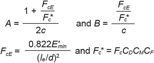 E'min = EminCM (see Appendix Table A-3.9 for adjustments to E and Emin) d = cross-sectional dimension (in.) corresponding to the unbraced length, le. Where the unbraced length is the same for both axes of the cross section, d should be taken as the smaller cross-sectional dimension; otherwise, use the larger value of le/d le = the unbraced length corresponding to the cross-sectional dimension, d c = 0.8 for sawn lumber, and 0.9 for glulam |
| E. Temperature factor, Ct | ||
|---|---|---|
| Temperature, T, (°F) | Ct (used dry) | Ct (used wet) |
| T ≤ 100°F | 1.0 | 1.0 |
| 100°F < T ≤ 125°F | 0.8 | 0.7 |
| 125°F < T ≤ 150°F | 0.7 | 0.5 |
Notes:
1. CF = 0.9 for all 2× or 4× dimension lumber having nominal width greater or equal to 14.
2. CM = 1.0 for dimension lumber when FcCF ≤ 750 psi.
3. Size factor adjustments are not used for compression perpendicular to grain.
4. Load duration adjustments are not used for compression perpendicular to grain.
5. Column stability factor adjustments are not used for compression perpendicular to grain.
6. Exceptions: CF = 1.05 for stud grade 2 × 2, 2 × 4, and 4 × 4 lumber; CF = 1.0 for construction and standard 2 × 2, 2 × 4, and 4 × 4 lumber; and CF = 0.6 for utility grade 2 × 2 lumber
7. Exceptions: CF = 1.0 for stud grade 2 × 6 and 4 × 6 lumber
8. Exceptions: For stud grade lumber with nominal width of 8 or higher, use No.3 grade values for Fc and CF
Table A-3.5: Design values for bending, Fb (psi) for visually-graded lumber and glued-laminated softwood timber timber
| A. Dimension lumber (2 in. – 4 in. thick) | |||||
|---|---|---|---|---|---|
| Species | Select Structural | No. 1 | No. 2 | No. 3 | Miscellaneous |
| Douglas Fir-Larch | 1500 | 1000 | 900 | 525 | 11200 |
| Douglas Fir-Larch (North) | 1350 | n/a | n/a | 475 | 2850 |
| Douglas Fir-South | 1350 | 925 | 850 | 500 | |
| Hem-Fir | 1400 | 975 | 850 | 500 | 11100 |
| Hem-Fir (North) | 1300 | n/a | n/a | 575 | 21000 |
| Spruce-Pine-Fir | 1250 | n/a | n/a | 500 | 2875 |
| Spruce-Pine-Fir (South) | 1300 | 875 | 775 | 450 | |
| Southern Pine3 | 1850 | 1175 | 950 | 550 | |
| B. Beams and stringers4 | |||||
|---|---|---|---|---|---|
| Species | Select Structural | No. 1 | No. 2 | No. 3 | Miscellaneous |
| Douglas Fir-Larch | 1600 | 1350 | 875 | n/a | |
| Douglas Fir-Larch (North) | 1600 | 1300 | 875 | n/a | |
| Douglas Fir-South | 1550 | 1300 | 825 | n/a | |
| Hem-Fir | 1300 | 1050 | 765 | n/a | |
| Hem-Fir (North) | 1250 | 1000 | 675 | n/a | |
| Spruce-Pine-Fir | 1100 | 900 | 600 | n/a | |
| Spruce-Pine-Fir (South) | 1050 | 900 | 575 | n/a | |
| Southern Pine5 | 1500 | 1350 | 850 | n/a | |
| C. Posts and timbers6 | |||||
|---|---|---|---|---|---|
| Species | Select Structural | No. 1 | No. 2 | No. 3 | Miscellaneous |
| Douglas Fir-Larch | 1500 | 1200 | 750 | n/a | |
| Douglas Fir-Larch (North) | 1500 | 1200 | 725 | n/a | |
| Douglas Fir-South | 1450 | 1150 | 675 | n/a | |
| Hem-Fir | 1200 | 975 | 575 | n/a | |
| Hem-Fir (North) | 1150 | 925 | 550 | n/a | |
| Spruce-Pine-Fir | 1050 | 850 | 500 | n/a | |
| Spruce-Pine-Fir (South) | 1000 | 800 | 475 | n/a | |
| Southern Pine5 | 1500 | 1350 | 850 | n/a | |
| D. Glued-laminated softwood timber | ||||||||
|---|---|---|---|---|---|---|---|---|
| Species | Grade (and Identification No.) | |||||||
| Fb (for beams with d > 15 in.) | Fb (for beams with d ≤ 15 in.) | |||||||
| Douglas Fir-Larch7 (DF) |
L3 (ID#1) 1100 |
L2 (ID#2) 1496 |
L2D (ID#3) 1760 |
L1 (ID#5) 1936 |
L3 (ID#1) 1250 |
L2 (ID#2) 1700 |
L2D (ID#3) 2000 |
L1 (ID#5) 2200 |
| Softwood Species7 (SW) |
L3 (ID#22) 638 |
L3 (ID#22) 725 | ||||||
| Alaska Cedar7 (AC) |
L3 (ID#69) 880 |
L2 (ID#70) 1188 |
L1D (ID#71) 1540 |
L1S (ID#72) 1672 |
L3 (ID#69) 1000 |
L2 (ID#70) 1350 |
L1D (ID#71) 1750 |
L1S (ID#72) 1900 |
| Southern Pine7 (SP) |
N2M12 (ID#47) 1232 |
N2D12 (ID#48) 1408 |
N1M16 (ID#49) 1584 |
N1D14 (ID#50) 1848 |
N2M12 (ID#47) 1400 |
N2D12 (ID#48) 1600 |
N1M16 (ID#49) 1800 |
N1D14 (ID#50) 2100 |
| Various species8 (SP) | Combination Symbols for Stress Classes | |||||||
| Fb (for positive bending9) | Fb (for negative bending9) | 16F-1.3E 1600 |
20F-1.5E 2000 |
24F-1.7E 2400 |
24F-1.8E 2400 |
16F-1.3E 925 |
20F-1.5E 1100 |
24F-1.7E 1450 |
24F-1.8E 1450 |
| E. Glued-laminated softwood timber bent about y-axis (loaded parallel to wide face of laminations) | ||||||||
|---|---|---|---|---|---|---|---|---|
| Species | Grade (and Identification No.) | |||||||
| Fb (for 4 or more laminations) | Fb (for 3 laminations) | |||||||
| Douglas Fir-Larch7 (DF) |
L3 (ID#1) 1450 |
L2 (ID#2) 1800 |
L2D (ID#3) 2100 |
L1 (ID#5) 2400 |
L3 (ID#1) 1250 |
L2 (ID#2) 1600 |
L2D (ID#3) 1850 |
L1 (ID#5) 2100 |
| Softwood Species7 (SW) |
L3 (ID#22) 800 |
L3 (ID#22) 700 | ||||||
| Alaska Cedar7 (AC) |
L3 (ID#69) 1100 |
L2 (ID#70) 1400 |
L1D (ID#71) 1850 |
L1S (ID#72) 1850 |
L3 (ID#69) 975 |
L2 (ID#70) 1250 |
L1D (ID#71) 1650 |
L1S (ID#72) 1650 |
| Southern Pine7 (SP) |
N2M12 (ID#47) 1750 |
N2D12 (ID#48) 2000 |
N1M16 (ID#49) 1950 |
N1D14 (ID#50) 2300 |
N2M12 (ID#47) 1550 |
N2D12 (ID#48) 1800 |
N1M16 (ID#49) 1750 |
N1D14 (ID#50) 2100 |
| Various species8 (SP) | Combination Symbols for Stress Classes | |||||||
| Fb (all cases) | ||||||||
| 16F-1.3E 800 |
20F-1.5E 800 |
24F-1.7E 1050 |
24F-1.8E 1450 |
|||||
Notes:
1. No.1 & better
2. No.1/No.2
3. Values for Southern Pine for dimension lumber are approximate: typical published values include the size factor and therefore list different values for each lumber width; whereas the values in this table have been normalized (i.e., do not include the size factor) and have been rounded down to values that may be slightly conservative.
4. Beams and stringers are a subset of the "timbers" size category, 5 in. × 5 in. or larger, where the width is at least 4 in. bigger than the thickness.
5. Southern Pine values for timbers (beams and stringers; posts and timbers) are for wet service conditions.
6. Posts and timbers are a subset of the "timbers" size category, 5 in. × 5 in. or larger, where the width is equal to, or no more than 2 in. bigger than, the thickness.
7. These species designations are designed primarily for axially-loaded elements (compression and tension), although they can be used for bending with the values that appear in this table. For bending about the x-axis only, these elements are assumed to have no special tension laminations; such special tension laminations would increase the bending design values (for all cross-section sizes bent about the x-axis) to the values shown for d ≤ 15 in. multiplied by a factor of 1.18.
8. These combination designations are designed primarily for simply-supported bending elements (i.e., for beams with only positive bending moments), and are manufactured with higher strength grades of wood used in the extreme fibers (for bending about the x-axis) where bending stresses are greatest.
9. The combination symbols in this table refer to cross sections that are "unbalanced"; i.e., they are manufactured to optimize the behavior of simply-supported beams with only positive curvature. Where such unbalanced combinations are used for beams subjected to negative bending moments — i.e., for continuous or cantilevered beams — lower values for Fb must be used at those cross sections with negative moment. For beams subjected to reversals of curvature (and therefore both positive and negative bending), "balanced" (symmetrical) combinations can be specified where Fb is the same for both positive and negative bending, for example: combination symbols 16F-V6 with Fb = 1600 psi; 20F-V7 with Fb = 2000 psi; and 24F-V8 with Fb = 2400 psi.
Table A-3.6: Adjustments to allowable stress in bending, Fb, for visually-graded lumber and glued-laminated softwood timber
| A. Size factor3 | |||
|---|---|---|---|
| Size factor, CF. (1) For glulam, size factor does not apply (use smaller of CV and CL — see Table A-3.6 Parts C and F below). (2) For timbers (beams and stringers; posts and timbers): when d > 12 in., CF = (12/d)1/9 ≤ 1; when loaded on the wide face, CF = 0.86 (select structural), 0.74 (No.1), or 1.00 (No.2); otherwise, CF = 1.00. (3) For dimension lumber, CF is as shown here: | |||
Size CF |
Size CF |
Size CF |
Size CF |
32 × 2 1.5 |
52 × 8 1.2 |
1,52 × 14 0.9 |
54 × 8 1.3 |
32 × 4 1.5 |
52 × 10 1.1 |
34 × 4 1.5 |
54 × 10 1.2 |
42 × 6 1.3 |
1,52 × 12, 4 × 14 1.0 |
44 × 6 1.3 |
1,54 × 12 1.1 |
| B. Flat use factor | |||
|---|---|---|---|
| Flat use factor, Cfu, is used only when dimension lumber (or glulam) is oriented about its weak axis: (1) For dimension lumber: | |||
Size Cfu |
Size Cfu |
Size Cfu |
Size Cfu |
2 × 4 1.10 |
2 × 10 1.20 |
4 × 6 1.05 |
4 × 12 1.10 |
2 × 6 1.15 |
2 × 12 1.20 |
4 × 8 1.05 |
4 × 14 1.10 |
2 × 8 1.15 |
2 × 14 1.20 |
4 × 10 1.10 |
4 × 16 1.10 |
(2) For glulam:
For glulam beams bent about their weak (y) axis, and where the depth, d < 12 in.: Cfu = (12/d)1/9 The approximate values shown below can be used as an alternative: 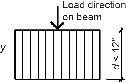 | |||
Depth, d (in.) Cfu |
Depth, d (in.) Cfu | ||
2-1/2 1.19 |
6-3/4 1.07 | ||
3 or 3-1/8 1.16 |
8-1/2 or 8-3/4 1.04 | ||
5 or 5-1/8 1.10 |
10-1/2 or 10-3/4 1.01 | ||
| C. Volume factor |
|---|
The volume factor, CV, is used only for glulam beams loaded about their strong axes, and only if smaller than CL (see below). For these conditions: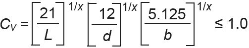 where L = the length of the simply-supported beam, or, for other beam types the distance between points of zero moment (ft) d = beam depth (in.) b = beam width (in.) x = 10 (except x = 20 for Southern Pine only) |
| D. Wet service factor |
|---|
| Wet service factor, CM, is as follows: for 2dimension lumber, CM = 0.85; for timbers, CM = 1.0; for glulam, CM = 0.8. In any dry service condition, CM = 1.0. |
| E. Repetitive member factor |
|---|
| Repetitive member factor, Cr = 1.15, is used only for dimension lumber spaced 24 in. on center or less (typically the case with joists and rafters). |
| F. Beam stability factor | |
|---|---|
| The beam stability factor, CL, may apply to glulam and timber beams, but not ordinarily to dimension lumber, and only when the compression edge of the beam is unbraced by a roof or floor deck. For continuously braced beams, i.e., when le = 0, CL = 0. For glulam, use only the smaller value of CL or CV. For timbers, combine CL with the size factor, CF. Use only when the beam depth is greater than its width. For these conditions, the beam stability factor, CL, is as follows: CL = A – where: 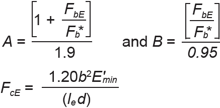 E'min = EminCM (see Appendix Table A-3.9 for adjustments to E and Emin) d = beam depth (in.) and b = beam width (in.) lu = the unsupported (unbraced) length (in.), i.e., the greatest distance between lateral braces, including bridging or blocking, along the length of the beam le = the effective unsupported length (in.) where continuous lateral support is not provided as shown in these selected loading patterns: | |
Load arrangement Effective length, le |
Load arrangement Effective length, le |
 Uniform load: no lateral support except at ends. le = 1.63lu + 3d for lu/d ≥ 7 le = 2.06lu for lu/d < 7 |
 Concentrated loads at third points: lateral support under loads and ends only. le = 1.68lu |
 Single concentrated load at midspan: no lateral support except at ends. le = 1.80lu for lu/d < 7 le = 1.37lu + 3d for lu/d ≥ 7 |
 Concentrated loads at quarter points: lateral support under loads and ends only. le = 1.54lu |
 Single concentrated load at midspan: lateral support under load and ends only. le = 1.11lu | |
| G. Load duration factor | |
|---|---|
| Load duration factor, CD, is as follows: | |
|
Load type Duration CD |
Load type Duration CD |
|
Dead load, D Permanent 0.90 |
Construction load, Lr 1 week 1.25 |
|
Live load, L 10 years 1.00 |
Wind or seismic load, W or E 10 minutes 1.60 |
|
Snow load, S 2 months 1.15 |
Impact load, I instant 2.00 |
| H. Temperature factor, Ct | ||
|---|---|---|
| Temperature, T, (°F) | Ct (used dry) | Ct (used wet) |
| T ≤ 100°F | 1.0 | 1.0 |
| 100°F < T ≤ 125°F | 0.8 | 0.7 |
| 125°F < T ≤ 150°F | 0.7 | 0.5 |
Notes:
1. CF = 0.9 for all 2× dimension lumber having nominal width greater or equal to 14. CF = 1.0 for all 4× dimension lumber having nominal width greater or equal to 14.
2. CM = 1.0 for dimension lumber when FbCF ≤ 1150 psi.
3. Exceptions: CF = 1.1 for stud grade 2 × 2, 2 × 4, and 4 × 4 lumber; CF = 1.0 for construction and standard 2 × 2, 2 × 4, and 4 × 4 lumber; and CF = 0.4 for utility grade 2 × 2 lumber
4. Exceptions: CF = 1.0 for stud grade 2 × 6 and 4 × 6 lumber
5. Exceptions: For stud grade lumber with nominal width of 8 in. or higher, use No.3 grade values for Fb and CF
Table A-3.7: Design values for shear, Fv (psi) for visually-graded lumber and glued-laminated softwood timber timber
| A. Dimension lumber (2 in. – 4 in. thick) | |||||
|---|---|---|---|---|---|
| Species | Select Structural | No. 1 | No. 2 | No. 3 | Miscellaneous |
| Douglas Fir-Larch | 180 | 180 | 180 | 180 | 1180 |
| Douglas Fir-Larch (North) | 180 | n/a | n/a | 180 | 2180 |
| Douglas Fir-South | 180 | 180 | 180 | 180 | |
| Hem-Fir | 150 | 150 | 150 | 150 | 1150 |
| Hem-Fir (North) | 145 | n/a | n/a | 145 | 2145 |
| Spruce-Pine-Fir | 135 | n/a | n/a | 135 | 2135 |
| Spruce-Pine-Fir (South) | 135 | 135 | 135 | 135 | |
| Southern Pine3 | 175 | 175 | 175 | 175 | |
| B. Timbers3 | |||||
|---|---|---|---|---|---|
| Species | Select Structural | No. 1 | No. 2 | No. 3 | Miscellaneous |
| Douglas Fir-Larch | 170 | 170 | 170 | n/a | |
| Douglas Fir-Larch (North) | 170 | 170 | 170 | n/a | |
| Douglas Fir-South | 165 | 165 | 165 | n/a | |
| Hem-Fir | 140 | 140 | 140 | n/a | |
| Hem-Fir (North) | 135 | 135 | 135 | n/a | |
| Spruce-Pine-Fir | 125 | 125 | 125 | n/a | |
| Spruce-Pine-Fir (South) | 125 | 125 | 125 | n/a | |
| Southern Pine5 | 165 | 165 | 165 | n/a | |
| C. Glued-laminated softwood timber bent about x-axis (loaded perpendicular to wide face of laminations) | ||||
|---|---|---|---|---|
| Species | Grade (and Identification No.) | |||
| Fv (for bending about x-axis7) | ||||
| Douglas Fir-Larch5 (DF) |
L3 (ID#1) 265 |
L2 (ID#2) 265 |
L2D (ID#3) 265 |
L1D L1 (ID#5) 265 |
| Softwood Species5,8 (SW) |
L3 (ID#22) 195 | |||
| Alaska Cedar5 (AC) |
L3 (ID#69) 265 |
L2 (ID#70) 265 |
L1D (ID#71) 265 |
L1S (ID#72) 265 |
| Southern Pine5 (SP) |
N2M14 N2M12 (ID#47) 300 |
N2D14 N2D12 (ID#48) 300 |
N1M16 (ID#49) 300 |
N1D14 (ID#50) 300 |
| Species | Combination Symbols for Stress Classes | |||
| Fv (for bending about x-axis7) | ||||
| Various species6 |
16F-1.3E 195 |
20F-1.5E 195 |
24F-1.7E 210 |
24F-1.8E 265 |
| D. Glued-laminated softwood timber bent about y-axis (loaded parallel to wide face of laminations) | ||||
|---|---|---|---|---|
| Species | Grade (and Identification No.) | |||
| Fv (for bending about x-axis7) | ||||
| Douglas Fir-Larch5 (DF) |
L3 (ID#1) 230 |
L2 (ID#2) 230 |
L2D (ID#3) 230 |
L1D L1 (ID#5) 230 |
| Softwood Species5,8 (SW) |
L3 (ID#22) 170 | |||
| Alaska Cedar5 (AC) |
L3 (ID#69) 230 |
L2 (ID#70) 230 |
L1D (ID#71) 230 |
L1S (ID#72) 230 |
| Southern Pine5 (SP) |
N2M14 N2M12 (ID#47) 260 |
N2D14 N2D12 (ID#48) 260 |
N1M16 (ID#49) 260 |
N1D14 (ID#50) 260 |
| Species | Combination Symbols for Stress Classes | |||
| Fv (for bending about x-axis7) | ||||
| Various species6 |
16F-1.3E 170 |
20F-1.5E 170 |
24F-1.7E 185 |
24F-1.8E 230 |
Notes:
1. No.1 & better
2. No.1/No.2
3. Timbers include "beams and stringers" and "posts and timbers," i.e., all cross sections 5 in. × 5 in. or larger.
4. Southern Pine values for timbers (beams and stringers; and posts and timbers) are for wet service conditions.
5. These species designations are designed primarily for axially-loaded elements (compression and tension), although they can be used for bending with the shear values that appear in this table.
6. These combination designations are designed primarily for bending elements, and are manufactured with higher strength grades of wood used in the extreme fibers where bending stresses are greatest when bent about the x-axis.
7. These values for horizontal shear must be reduced by a factor of 0.72 when used in the design of mechanical connections.
8. The design values for Fv shown for "softwood species" must be reduced by 10 psi (before adjustments are considered) when the following species are used in combination: Coast Sitka Spruce, Coast Species, Western White Pine, and Eastern White Pine.
Table A-3.8: Adjustments to allowable stress in shear, Fv, for visually-graded lumber and glued-laminated softwood timber
| A. Wet service factor |
|---|
| Wet service factor, CM is as follows: for dimension lumber, CM = 0.97; for timbers, CM = 1.0; for glulam, CM = 0.875. In any dry service condition, CM = 1.0. |
| B. Load duration factor | |
|---|---|
| Load duration factor, CD, is as follows: | |
|
Load type Duration CD |
Load type Duration CD |
|
Dead load, D Permanent 0.90 |
Construction load, Lr 1 week 1.25 |
|
Live load, L 10 years 1.00 |
Wind or seismic load, W or E 10 minutes 1.60 |
|
Snow load, S 2 months 1.15 |
Impact load, I instant 2.00 |
| C. Temperature factor, Ct | ||
|---|---|---|
| Temperature, T, (°F) | Ct (used dry) | Ct (used wet) |
| T ≤ 100°F | 1.0 | 1.0 |
| 100°F < T ≤ 125°F | 0.8 | 0.7 |
| 125°F < T ≤ 150°F | 0.7 | 0.5 |
Table A-3.9: Design values for modulus of elasticity, E and Emin (psi) for visually graded lumber and glued-laminated timber (values and adjustments)
| A. Modulus of elasticity, E (psi)5 | |||||
|---|---|---|---|---|---|
| Dimension lumber (2 in. – 4 in. thick) | Select Structural | No. 1 | No. 2 | No. 3 | Miscellaneous |
| Douglas Fir-Larch | 1,900,000 | 1,700,000 | 1,600,000 | 1,400,000 | 11,800,000 |
| Douglas Fir-Larch (North) | 1,900,000 | n/a | n/a | 1,400,000 | 21,600,000 |
| Douglas Fir-South | 1,400,000 | 1,300,000 | 1,200,000 | 1,100,000 | |
| Hem-Fir | 1,600,000 | 1,500,000 | 1,300,000 | 1,200,000 | 11,500,000 |
| Hem-Fir (North) | 1,700,000 | n/a | n/a | 1,400,000 | 21,600,000 |
| Spruce-Pine-Fir | 1,500,000 | n/a | n/a | 1,200,000 | 21,400,000 |
| Spruce-Pine-Fir (South) | 1,300,000 | 1,200,000 | 1,100,000 | 1,000,000 | |
| Southern Pine | 1,800,000 | 1,700,000 | 1,600,000 | 1,400,000 | Timbers3 | Select Structural | No. 1 | No. 2 | No. 3 | Miscellaneous |
| Douglas Fir-Larch | 1,600,000 | 1,600,000 | 1,300,000 | n/a | |
| Douglas Fir-Larch (North) | 1,600,000 | 1,600,000 | 1,300,000 | n/a | |
| Douglas Fir-South | 1,200,000 | 1,200,000 | 1,100,000 | n/a | |
| Hem-Fir | 1,300,000 | 1,300,000 | 1,100,000 | n/a | |
| Hem-Fir (North) | 1,300,000 | 1,300,000 | 1,100,000 | n/a | |
| Spruce-Pine-Fir | 1,300,000 | 1,300,000 | 1,100,000 | n/a | |
| Spruce-Pine-Fir (South) | 1,200,000 | 1,200,000 | 1,000,000 | n/a | |
| Southern Pine | 1,500,000 | 1,500,000 | 1,200,000 | n/a | |
| Glued-Laminated Software Timber | Grade (and Identification No.) | ||||
| Douglas Fir-Larch7 (DF) |
L3 (ID#1) 1,500,000 |
L2 (ID#2) 1,600,000 |
L2D (ID#3) 1,900,000 |
L1 (ID#5) 2,000,000 | |
| Softwood Species7,9 (SW) |
L3 (ID#22) 1,000,000 | ||||
| Alaska Cedar7 (AC) |
L3 (ID#69) 1,400,000 |
L2 (ID#70) 1,700,000 |
L1D (ID#71) 1,700,000 |
L1S (ID#72) 1,900,000 | |
| Southern Pine7 (SP) |
N2M12 (ID#47) 1,400,000 |
N2D12 (ID#48) 1,700,000 |
N1M16 (ID#49) 1,700,000 |
N1D14 (ID#50) 1,900,000 | |
| Combination Symbols for Stress Classes | |||||
| Various species (bending about x-axis)8 | 16F-1.3E 1,300,000 |
20F-1.5E 1,500,000 |
24F-1.7E 1,700,000 |
24F-1.8E 1,800,000 | |
| Various species (bending about y-axis)8 | 16F-1.3E 1,100,000 |
20F-1.5E 1,200,000 |
24F-1.7E 1,300,000 |
24F-1.8E 1,600,000 | |
| B. Modulus of elasticity, Emin (psi)6 | |||||
|---|---|---|---|---|---|
| Dimension lumber (2 in. – 4 in. thick) | Select Structural | No. 1 | No. 2 | No. 3 | Miscellaneous |
| Douglas Fir-Larch | 690,000 | 620,000 | 580,000 | 510,000 | 1660,000 |
| Douglas Fir-Larch (North) | 690,000 | n/a | n/a | 510,000 | 2580,000 |
| Douglas Fir-South | 510,000 | 470,000 | 440,000 | 400,000 | |
| Hem-Fir | 580,000 | 550,000 | 470,000 | 440,000 | 1550,000 |
| Hem-Fir (North) | 620,000 | n/a | n/a | 510,000 | 2580,000 |
| Spruce-Pine-Fir | 550,000 | n/a | n/a | 440,000 | 2510,000 |
| Spruce-Pine-Fir (South) | 470,000 | 440,000 | 400,000 | 370,000 | |
| Southern Pine | 660,000 | 620,000 | 580,000 | 510,000 | Timbers3 | Select Structural | No. 1 | No. 2 | No. 3 | Miscellaneous |
| Douglas Fir-Larch | 580,000 | 580,000 | 470,000 | n/a | |
| Douglas Fir-Larch (North) | 580,000 | 580,000 | 470,000 | n/a | |
| Douglas Fir-South | 440,000 | 440,000 | 370,000 | n/a | |
| Hem-Fir | 470,000 | 470,000 | 400,000 | n/a | |
| Hem-Fir (North) | 470,000 | 470,000 | 400,000 | n/a | |
| Spruce-Pine-Fir | 470,000 | 470,000 | 370,000 | n/a | |
| Spruce-Pine-Fir (South) | 440,000 | 440,000 | 370,000 | n/a | |
| Southern Pine | 550,000 | 550,000 | 440,000 | n/a | |
| Glued-Laminated Software Timber | Grade (and Identification No.) | ||||
| Douglas Fir-Larch7 (DF) |
L3 (ID#1) 790,000 |
L2 (ID#2) 850,000 |
L2D (ID#3) 1,000,000 |
L1 (ID#5) 1,060,000 | |
| Softwood Species7,9 (SW) |
L3 (ID#22) 530,000 | ||||
| Alaska Cedar7 (AC) |
L3 (ID#69) 630,000 |
L2 (ID#70) 690,000 |
L1D (ID#71) 850,000 |
L1S (ID#72) 850,000 | |
| Southern Pine7 (SP) |
N2M12 (ID#47) 740,000 |
N2D12 (ID#48) 900,000 |
N1M16 (ID#49) 900,000 |
N1D14 (ID#50) 1,000,000 | |
| Combination Symbols for Stress Classes | |||||
| Various species (bending about x-axis)8 | 16F-1.3E 690,000 |
20F-1.5E 790,000 |
24F-1.7E 900,000 |
24F-1.8E 1,000,000 | |
| Various species (bending about y-axis)8 | 16F-1.3E 580,000 |
20F-1.5E 630,000 |
24F-1.7E 690,000 |
24F-1.8E 850,000 | |
| C. Wet service adjustment (CM) to E and Emin |
|---|
| Wet service factor, where applicable, is as follows: for dimension lumber, CM = 0.9; for glulam, CM = 0.833; for any other condition, CM = 1.0. In any dry service condition, CM = 1.0. |
| D. Temperature factor adjustment (Ct) to E and Emin | |
|---|---|
| Temperature, T, (°F) | Ct |
| T ≤ 100°F | 1.0 |
| 100°F < T ≤ 150°F | 0.9 |
Notes:
1. No.1 & better
2. No.1/No.2
3. Timbers include "beams and stringers" and "posts and timbers," i.e., all cross sections 5 in. × 5 in. or larger.
4. Southern Pine values for timbers (beams and stringers; and posts and timbers) are for wet service conditions.
5. The modulus of elasticity, E, is an average value, used in the calculation of beam deflections, but not for column or beam stability calculations.
6. The minimum modulus of elasticity, Emin, is a conservative (low) value, based on statistical analyses of moduli for tested samples, and is used in calculations of column buckling (CP) and beam stability (CL).
7. These species designations are designed primarily for axially-loaded elements (compression and tension), although they can be used in any context with the values that appear in this table.
8. These combination designations are designed primarily for bending elements, although they can be used in any context with the values that appear in this table.
9. The design values for E shown for "softwood species" must be reduced from 1,000,000 psi to 900,000 psi when the following species are used in combination: Western Cedars, Western Cedars (North), Western Woods, and Redwood (open grain).
10. The design values for Emin shown for "softwood species" must be reduced from 530,000 psi to 477,200 psi when the following species are used in combination: Western Cedars, Western Cedars (North), Western Woods, and Redwood (open grain).
Table A-3.10: Use of load duration factor, CD, for wood elements
| Where more than one load type acts on a wood structural element, CD corresponds to the load of shortest duration. Values of CD for tension, compression, bending, and shear can be found in Appendix Tables A-3.2, A-3.4, A-3.6, and A-3.8 respectively. It is sometimes necessary to check various combinations of loads (where the corresponding value of CD changes) to determine the critical loading condition. Since the strength of lumber depends on the duration of loading, it is possible that a smaller load, with a longer duration, will be more critical than a larger load that acts on the element for less time. For example, consider a wooden column supporting the following loads:
Lr and S are not considered simultaneously since it is unlikely that roof maintenance or construction will occur during a major snow storm. Several load combinations should be analyzed, per Chapter 2 Appendix Table A-2.7 (using Allowable Stress Design for wood): 1. D + L with CD = 1.0 (corresponding to the live load). 2. D + S with CD = 1.15 (corresponding to the snow load). 3. D + 0.75L + 0.75S with CD = 1.15 (corresponding to the snow load). It is usually unnecessary to go through the entire design procedure for each load combination; instead, divide the loads in each case by the corresponding load duration factor to get a measure of the relative "load effects;" that is: 1. (15,000 + 20,000)/1.00 = 35,000/1.0 = 35,000 lb; 2. (15,000 + 8,000)/1.15 = 23,000/1.15 = 20,000 lb; 3. (15,000 + 0.75 × 20,000 + 0.75 × 16,000)/1.15 = 42,000/1.15 = 36,522 lb. The third load combination is the critical one in this case, based on the underlined value being largest of the three choices. However, the structural element should be designed for the bold-faced value of 42,000 lb, and not the underlined value of 36,522 lb which is used only to determine the governing load value. The governing duration of load factor, CD = 1.15, will then be applied, not to the loads, but to the allowable stress. Where only "occupancy" live loads and dead loads are present, CD can almost always be taken as 1.0 (corresponding to the load duration factor for live loads). The case of dead load acting alone, with CD = 0.9, is critical only when more than 90% of the total load is dead load. |
Table A-3.11: Specific gravity for selected wood species ((based on oven-dry weight and volume)
Species or Species Combination Specific Gravity |
Species or Species Combination Specific Gravity |
|---|---|
Douglas Fir-Larch 0.50 |
Hem-Fir (North) 0.46 |
Douglas Fir-Larch (North) 0.49 |
Spruce-Pine-Fir 0.42 |
Douglas Fir-South 0.46 |
Spruce-Pine-Fir (South) 0.36 |
Hem-Fir 0.43 |
Southern Pine 0.55 |
Table A-3.12: Dimensions and properties of lumber1
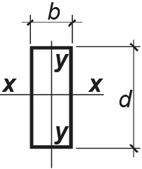 Properties of rectangular cross sections: Cross-sectional area, A = bd Section modulus, Sx = bd2/6 Moment of inertia, Ix = bd3/12 Moment of inertia, Iy = db3/12 |
| A. Dimension lumber | |||||
|---|---|---|---|---|---|
| Dimension lumber nominal size | Actual size, b × d (in.) | Area (in2) | Sx (in3) | Ix (in4) | Iy (in4) |
| 2 × 3 2 × 4 2 × 6 2 × 8 2 × 10 2 × 12 2 × 14 |
1.5 × 2.5 1.5 × 3.5 1.5 × 5.5 1.5 × 7.25 1.5 × 9.25 1.5 × 11.25 1.5 × 13.25 |
3.75 5.25 8.25 10.88 13.88 16.88 19.88 |
1.563 3.063 7.563 13.14 21.39 31.64 43.89 |
1.953 5.359 20.80 47.63 98.93 178.0 290.8 |
0.703 0.984 1.547 2.039 2.602 3.164 3.727 |
| 4 × 4 4 × 6 4 × 8 4 × 10 4 × 12 4 × 14 4 × 16 |
3.5 × 3.5 3.5 × 5.5 3.5 × 7.25 3.5 × 9.25 3.5 × 11.25 3.5 ×13.25 3.5 × 15.25 |
12.25 19.25 25.38 32.38 39.38 46.38 53.38 |
7.146 17.65 30.66 49.91 73.83 102.4 135.7 |
12.51 48.53 111.1 230.8 415.3 678.5 1034.4 |
12.51 19.65 25.90 33.05 40.20 47.34 54.49 |
| B. Beams and stringers | |||||
|---|---|---|---|---|---|
| Beams + Stringers nominal size | Actual size1, b × d (in.) | Area (in2) | Sx (in3) | Ix (in4) | Iy (in4) |
| 6 × 10 6 × 12 6 × 14 6 × 16 6 × 18 6 × 20 6 × 22 |
5.5 × 9.5 5.5 × 11.5 5.5 × 13.5 5.5 × 15.5 5.5 × 17.5 5.5 × 19.5 5.5 × 21.5 |
52.25 63.25 74.25 85.25 96.25 107.3 118.3 |
82.73 121.2 187.1 220.2 280.7 348.6 423.7 |
393.0 697.1 1128 1707 2456 3398 4555 |
131.7 159.4 187.2 214.9 242.6 270.4 298.1 |
| 8 × 12 8 × 14 8 × 16 8 × 18 8 × 20 8 × 22 8 × 24 |
7.5 × 11.5 7.5 × 13.5 7.5 × 15.5 7.5 × 17.5 7.5 × 19.5 7.5 × 21.5 7.5 × 23.5 |
86.3 101.3 116.3 131.3 146.3 161.3 176.3 |
165.3 227.8 300.3 382.8 475.3 577.8 690.3 |
950.5 1538 2327 3350 4634 6211 8111 |
404.3 474.6 544.9 615.2 685.5 755.9 826.2 |
| 10 × 14 10 × 16 10 × 18 10 × 20 10 × 22 10 × 24 |
9.5 × 13.5 9.5 × 15.5 9.5 × 17.5 9.5 × 19.5 9.5 × 21.5 9.5 × 23.5 |
128.3 147.3 166.3 185.3 204.3 270.3 |
288.6 380.4 484.9 728.8 731.9 874.4 |
1948 2948 4243 5870 7868 10274 |
964.5 1107 1250 1393 1536 1679 |
| 12 × 16 12 × 18 12 × 20 12 × 22 12 × 24 |
11.5 × 15.5 11.5 × 17.5 11.5 × 19.5 11.5 × 21.5 11.5 × 23.5 |
178.3 201.3 224.3 247.3 270.3 |
460.5 587.0 728.8 886.0 1058 |
3569 5136 7106 9524 12437 |
1964 2218 2471 2725 2978 |
| 14 × 18 14 × 20 14 × 22 14 × 24 |
13.5 × 17.5 13.5 × 19.5 13.5 × 21.5 13.5 × 23.5 |
236.3 263.3 290.3 317.3 |
689.1 855.6 1040 1243 |
6029 8342 11181 14600 |
3588 3998 4408 4818 |
| 16 × 20 16 × 22 16 × 24 |
15.5 × 19.5 15.5 × 21.5 15.5 × 23.5 |
302.3 333.3 364.3 |
982.3 1194 1427 |
9578 12837 16763 |
6051 6872 7293 |
| C. Posts and timbers | |||||
|---|---|---|---|---|---|
| Posts + Timbers nominal size | Actual size1, b × d (in.) | Area (in2) | Sx (in3) | Ix (in4) | Iy (in4) |
| 6 × 6 6 × 8 |
5.5 × 5.5 5.5 × 7.5 |
30.25 41.25 |
27.73 51.56 |
76.26 193.4 |
76.26 104.0 |
| 8 × 8 8 × 10 |
7.5 × 7.5 7.5 × 9.5 |
56.25 71.25 |
70.31 112.8 |
263.7 535.9 |
263.7 334.0 |
| 10 × 10 10 × 12 |
9.5 × 9.5 9.5 × 11.5 |
90.25 109.3 |
142.9 209.4 |
678.8 1204 |
678.8 821.7 |
| 12 × 12 12 × 14 |
11.5 × 11.5 11.5 × 13.5 |
132.3 155.3 |
253.5 349.3 |
1458 2358 |
1458 1711 |
| 14 × 14 14 × 16 |
13.5 × 13.5 13.5 × 15.5 |
182.3 209.3 |
410.1 540.6 |
2768 4189 |
2768 3178 |
| 16 × 16 16 × 18 |
15.5 × 15.5 15.5 × 17.5 |
240.3 271.3 |
620.6 791.1 |
4810 6923 |
4810 5431 |
| 18 × 18 18 × 20 |
17.5 × 17.5 17.5 × 19.5 |
306.3 341.3 |
893.2 1109 |
7816 10813 |
7816 8709 |
Note:
1. Actual sizes shown for "beams and stringers" and "posts and timbers" are minimum green dimensions — used for calculating the section properties listed in this table. For minimum dry sizes of these timbers, subtract 1/2 inch for 6-inch nominal dimensions, 3/4 inch for nominal dimensions greater than 6 and less than 16, and 1 inch for nominal dimensions 16 inches or greater.
Table A-3.13: Dimensions of typical glulam posts and beams1 (in.)
| Southern Pine (1-3/8 in. laminations) | Western Species2 (1-1/2 in. laminations) |
|---|---|
Width (in.) Depth (in.) |
Width (in.) Depth (in.) |
2-1/8 5-1/2 to 24-3/4 |
2-1/8 6 to 27 |
3 or 3-1/8 5-1/2 to 24-3/4 |
3-1/8 6 to 27 |
5 or 5-1/8 5-1/2 to 35-3/4 |
5-1/8 6 to 36 |
6-3/4 6-7/8 to 48-1/8 |
6-3/4 7-1/2 to 48 |
8-1/2 8-1/4 to 63-1/4 |
8-3/4 9 to 63 |
10-1/2 9-5/8 to 77 |
10-3/4 10-1/2 to 81 |
12 11 to 86-5/8 |
12-1/4 12 to 88-1/2 |
14 13-3/4 to 100-3/8 |
14-1/4 13-1/2 to 102 |
Notes:
1. Values are for premium, architectural, and industrial appearance grades; framing appearance grades are generally surfaced less so that they match standard lumber widths, e.g., 2-1/2 in., 3-1/2 in., 5-1/2 in., and 7-1/4 in.
2. Western Species (WS) consists of numerous species groups, not all of which are produced in the western US, including: Alaska Cedar (AC); Douglas Fir-Larch (DF) and Douglas Fir South (DFS); Eastern Spruce (ES), Hem-Fir (HF); Softwood Species (SW); andSpruce Pine Fir (SPF).
Table A-3.14: Allowable force (lb) based on row and group tear-out1,2
| Row tear-out | Group tear-out |
|---|---|
| Z'RT = rnn1(Fv')scrit(t) | Z'GRT = n1(Fv')scrit(t) + Ft'At |
Notes:
1. The terms in the equations for Z'RT and Z'GRT are defined as follows:
Z'RT = the maximum force that can be safely resisted by all fasteners subjected to row tear-out (lb)
Z'GRT = the maximum force that can be safely resisted by all fasteners subjected to group tear-out (lb)
rn = the number of rows of fasteners
n1 = the number of fasteners in a typical row
Fv' = the adjusted allowable shear stress for the wood element (psi)
Ft' = the adjusted allowable tension stress for the wood element (psi)
At = the area subjected to tension stress between the top and bottom rows of fasteners (in2)
scrit = the minimum spacing between fasteners, or the distance of the first fastener to the end of the member, if smaller (inches)
t = the member thickness (inches)
2. Row and group tear-out apply to wood tension members when the following conditions are met: (a) the direction of the tension force is parallel to the grain of the tension element; (b) the fasteners consist of bolts or lag screws; and (c) the connection consists of multiple fasteners in a row for row tear-out; and multiple rows of fasteners for group tear-out.
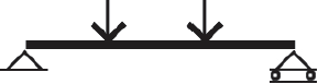
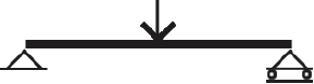
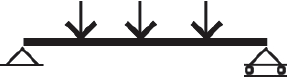
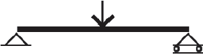
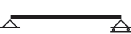
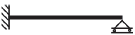
Table A-3.15: Maximum (actual) deflection in a beam1,2,3
Deflection coefficient, C, for maximum (actual) deflection, Δ (in.), where Δ = 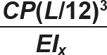 | ||||
 |  |  |  | |
 | 22.46 | 9.33 | 4.49 | 216 |
 | 35.94 | 16.07 | 8.99 | n/a |
 | 61.34 | 26.27 | 13.31 | n/a |
 | 85.54 | 36.12 | 17.97 | n/a |
 | n/a | n/a | n/a | 576 |
Notes:
1. Beam diagram symbols in top row of tables represent the following conditions (from left to right): simply-supported; one end pinned and one end continuous; both ends continuous; and cantilever.
2. Units for the maximum (actual) deflection equation are as follows:
Δ = maximum (actual) deflection (in.)
C = deflection coefficient
L = span (in.): The quantity (L/12) that appears in the deflection equation is therefore the span in feet
E = modulus of elasticity (psi when load is in lb; or ksi when load is in kips)
Ix = moment of inertia about axis of bending (in4)
P = concentrated load or resultant of uniformly-distributed load (lb or kips)
w = uniformly-distributed load (lb/ft or kips/ft)
3. Allowable deflections (from Appendix Table A-1.3) are as follows:
For live load only (or snow or wind only), the typical basic floor beam limit is L/360 while typical roof beam limits are L/180, L/240, or L/360 (for no ceiling, nonplaster ceiling, or plaster ceiling respectively).
For total loads (combined live and dead), the typical basic floor beam limit is L/240 while typical roof beam limits are L/120, L/180, or L/240 (for no ceiling, nonplaster ceiling, or plaster ceiling respectively).
Table A-3.16: "Adjusted" section modulus (CFSx) values for wood sections in bending (lightest shown in bold face)1,2
Shape CFSx (in3) |
Shape CFSx (in3) |
Shape CFSx (in3) |
|---|---|---|
2 × 4 4 4.594 |
6 × 10 82.73 |
8 × 22 541.6 |
Double 2 × 4 9.188 |
Triple 2 × 12 94.92 |
12 × 18 562.9 |
2 × 6 9.831 |
4 × 14 102.4 |
10 × 20 570.4 |
Triple 2 × 4 13.78 |
Triple 2 × 14 118.5 |
8 × 24 640.6 |
2 × 8 15.77 |
6 × 12 121.2 |
14 × 18 660.8 |
Double 2 × 6 19.66 |
4 × 16 135.7 |
10 × 22 686.0 |
4 × 6 22.94 |
6 × 14 164.9 |
12 × 20 690.5 |
2 × 10 25.53 |
8 × 12 165.3 |
14 × 20 810.6 |
Triple 2 × 6 29.49 |
6 × 16 214.1 |
10 × 24 811.5 |
Double 2 × 8 31.54 |
8 × 14 224.9 |
12 × 22 830.4 |
2 × 12 31.64 |
6 × 18 269.2 |
16 × 20 930.7 |
2 × 14 39.50 |
10 × 14 284.8 |
14 × 22 974.8 |
4 × 8 39.86 |
8 × 16 291.9 |
12 × 24 982.3 |
Double 2 × 10 47.06 |
6 × 20 330.3 |
16 × 22 1119 |
Triple 2 × 8 47.31 |
8 × 18 367.1 |
14 × 24 1153 |
4 × 10 59.89 |
10 × 16 369.7 |
18 × 22 1264 |
Double 2 × 12 63.28 |
6 × 22 397.1 |
16 × 24 1324 |
Triple 2 × 10 70.59 |
12 × 16 447.6 |
20 × 22 1408 |
Double 2 × 14 79.00 |
8 × 20 450.4 |
18 × 24 1495 |
4 × 12 81.21 |
10 × 18 465.0 |
20 × 24 1666 |
Notes:
1. "Double" or "triple" indicates that two or three sections, respectively, are nailed together to create a single bending element.
2. The "adjusted" section modulus consists of the size factor, CF, multiplied by the section modulus, Sx.
Table A-3.17: Selected lag screw (lag bolt) dimensions
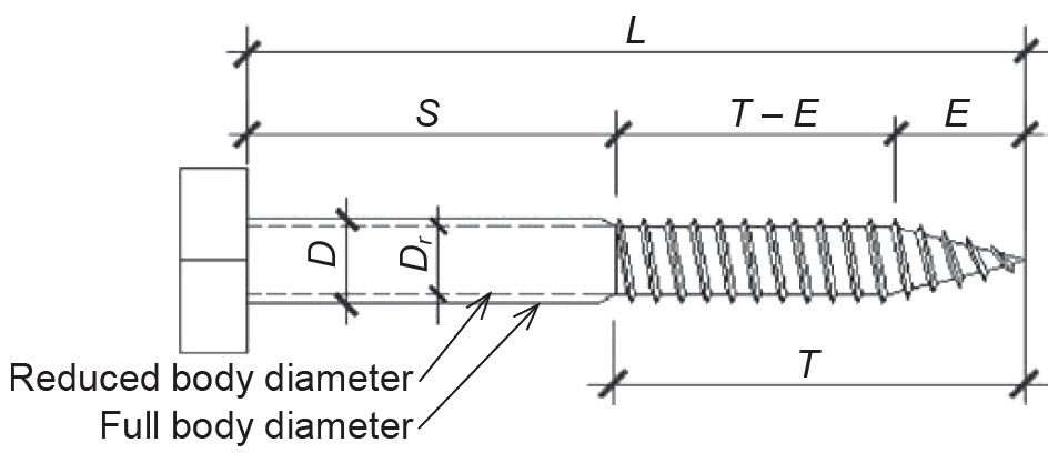 | |||||
| L (in.) | D (in.) | Dr (in.) | T (in.) | T – E (in.) | E (in.) |
|---|---|---|---|---|---|
| 3 | 0.250 | 0.173 | 2.0 | 1.8438 | 0.1562 |
| 3 | 0.375 | 0.265 | 2.0 | 1.7813 | 0.2187 |
| 3 | 0.500 | 0.371 | 2.0 | 1.6875 | 0.3125 |
| 3 | 0.625 | 0.471 | 2.0 | 1.5938 | 0.4062 |
| 4 | 0.250 | 0.173 | 2.5 | 2.3438 | 0.1562 |
| 4 | 0.375 | 0.265 | 2.5 | 2.2813 | 0.2187 |
| 4 | 0.500 | 0.371 | 2.5 | 2.1875 | 0.3125 |
| 4 | 0.625 | 0.471 | 2.5 | 2.0938 | 0.4062 |
| 5 | 0.250 | 0.173 | 3.0 | 2.8438 | 0.1562 |
| 5 | 0.375 | 0.265 | 3.0 | 2.7813 | 0.2187 |
| 5 | 0.500 | 0.371 | 3.0 | 2.6875 | 0.3125 |
| 5 | 0.625 | 0.471 | 3.0 | 2.5938 | 0.4062 |
| 6 | 0.250 | 0.173 | 3.5 | 3.3438 | 0.1562 |
| 6 | 0.375 | 0.265 | 3.5 | 3.2813 | 0.2187 |
| 6 | 0.500 | 0.371 | 3.5 | 3.1875 | 0.3125 |
| 6 | 0.625 | 0.471 | 3.5 | 3.0938 | 0.4062 |
Table A-3.18: Selected common wire nail dimensions
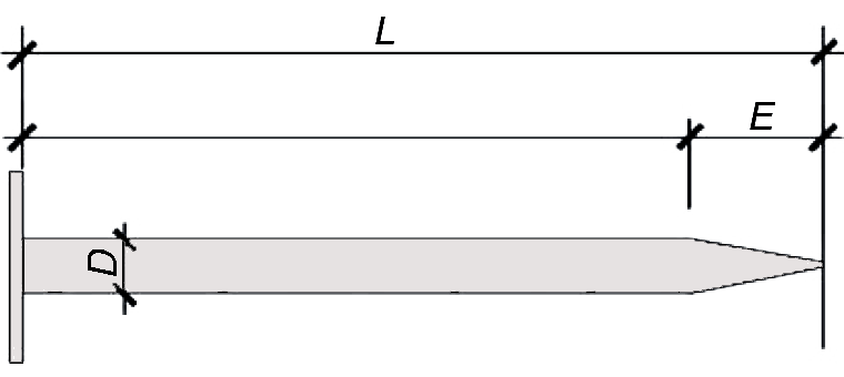 | |||
| Designation1 | L (in.) | D (in.) | 2E (in.) |
|---|---|---|---|
| 6d | 2.00 | 0.113 | 0.226 |
| 8d | 2.50 | 0.131 | 0.262 |
| 10d | 3.00 | 0.148 | 0.296 |
| 12d | 3.25 | 0.148 | 0.296 |
| 16d | 3.50 | 0.162 | 0.324 |
| 20d | 4.00 | 0.192 | 0.384 |
| 30d | 4.50 | 0.207 | 0.414 |
| 40d | 5.00 | 0.225 | 0.450 |
| 50d | 5.50 | 0.244 | 0.488 |
Notes:
1. The designation for nails once had some relation to the cost of 100 nails; it now refers only to the nail's size. The letter "d" in the designation refers to the pennyweight of the nails and is said to be derived from the biblical use of denarius (hence "d") as the historical equivalent of the modern penny (hence "pennyweight"). We continue to use the abbreviation "d" to stand for "penny" and we say "10-penny nail" when reading "10d nail."
2. E = approximate length of tapered tip, assumed to be equal to 2D.
Table A-3.19: Penetration and dowel bearing length1
| Type of fastener | Required penetration distance, p | |
|---|---|---|
| Absolute minimum | Minimum for full value of Z | |
Lag screw2 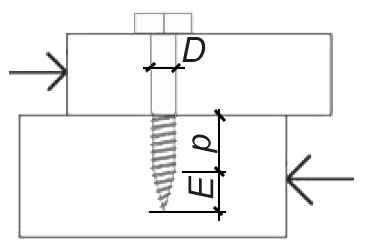 | 4D | 8D |
Nail3 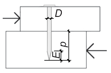 | 6D | 10D |
Bolt4 | n/a | n/a |
Notes:
1. The dowel bearing length in the main member (lm), used in yield limit calculations, may be different from the penetration as defined in the illustrations above: for lag screws, the dowel bearing length in the main member equals the penetration (which excludes the tapered tip); however, for nailed connections, the dowel bearing length in the main member equals the penetration (which includes the tapered tip) minus half the length of the tapered tip.
2. For lag screws where the penetration, p, falls between the two values shown in the table, the lateral design value, Z, is multiplied by p/(8D). Therefore, where the penetration equals the absolute minimum value of 4D, the lateral design value is taken as one half the tabular (or computed) value of Z.
3. For nails where the penetration, p, falls between the two values shown in the table, the lateral design value, Z, is multiplied by p/(10D). Therefore, where the penetration equals the absolute minimum value of 6D, the lateral design value is taken as 0.6 times the tabular (or computed) value of Z.
4. For bolts, "penetration" is always, by definition, 100% through both the main member and side member(s), so there is no need to calculate its effect on the lateral design value, Z.
Table A-3.20: Duration of load adjustment factor, CD, for wood connectors1
| C. Load duration factor | |
|---|---|
| Load duration factor, CD, is as follows: | |
|
Load type Duration CD |
Load type Duration CD |
|
Dead load, D Permanent 0.90 |
Construction load, Lr 1 week 1.25 |
|
Live load, L 10 years 1.00 |
Wind load, W 10 minutes 1.60 |
|
Snow load, S 2 months 1.15 |
Seismic load, E 10 minutes 1.60 |
Note:
1. Applies to both dowel-type connectors and connectors subject to withdrawal loads
Table A-3.21: Wet service adjustment factor, CM, for wood connectors1,2
| Fastener type with lateral load | CM | "Dowel-type," wet when made, dry in-service: • 1 fastener only • 2 or more fasteners in single row parallel to grain • Multiple rows of fasteners parallel to grain, separate splice plate each row • Fastener with diameter < 1/4 in. • Multiple rows of fasteners with diameter ≥ 1/4 in., without separate splice plates "Dowel-type," wet when used (in-service) |
varies as follows: 1.00 1.00 1.00 0.70 0.40 0.70 |
|---|---|
| Fastener type with withdrawal load | CM |
| Nails, wet when made, dry in-service Nails, dry when made, wet in-service Nails, wet when made, wet in-service Lag screws and wood screws, wet in-service |
0.25 0.25 1.00 0.70 |
Notes:
1. Applies to both dowel-type connectors and connectors subject to withdrawal loads.
2. CM = 1.0 for fasteners that are dry when fabricated and when used (in-service).
Table A-3.22: Group action adjustment factor, Cg, for wood connectors1,2,3,4
| A. Cg, bolt (or lag screw) connections, wood members with same properties: E = 1,400,000 psi; bolt or lag screw diameter, D = 3/4 in.; spacing between fasteners in a row, s = 3 in. | ||||||||||
|---|---|---|---|---|---|---|---|---|---|---|
| Am = Area of main member, in2 | number fasteners in row | As = Area of side member(s), in2 | ||||||||
| 5 | 8 | 11 | 14 | 17 | 30 | 40 | 56 | 64 | ||
| 5 | 2 3 4 5 6 7 8 9 10 |
1.000 0.984 0.954 0.914 0.867 0.817 0.766 0.716 0.669 |
0.991 0.962 0.918 0.866 0.809 0.752 0.698 0.647 0.601 |
0.987 0.952 0.902 0.844 0.783 0.723 0.667 0.616 0.570 |
0.985 0.947 0.893 0.831 0.768 0.707 0.650 0.598 0.552 |
0.983 0.943 0.887 0.823 0.758 0.696 0.638 0.587 0.540 |
0.980 0.936 0.875 0.807 0.739 0.675 0.616 0.563 0.517 |
0.979 0.933 0.871 0.802 0.733 0.688 0.608 0.556 0.510 |
0.978 0.931 0.868 0.798 0.728 0.662 0.602 0.549 0.503 |
0.978 0.931 0.867 0.796 0.726 0.660 0.600 0.547 0.501 |
| 8 | 2 3 4 5 6 7 8 9 10 |
0.991 0.962 0.918 0.866 0.809 0.752 0.698 0.647 0.601 |
1.000 0.990 0.971 0.943 0.910 0.873 0.833 0.792 0.751 |
0.996 0.979 0.953 0.918 0.877 0.834 0.790 0.746 0.704 |
0.993 0.973 0.942 0.903 0.859 0.812 0.766 0.720 0.677 |
0.992 0.970 0.936 0.894 0.847 0.798 0.750 0.703 0.659 |
0.989 0.962 0.922 0.875 0.823 0.770 0.719 0.670 0.624 |
0.988 0.959 0.918 0.869 0.815 0.761 0.708 0.659 0.613 |
0.987 0.957 0.914 0.863 0.809 0.753 0.700 0.650 0.603 |
0.987 0.956 0.913 0.862 0.806 0.751 0.697 0.647 0.600 |
| 11 | 2 3 4 5 6 7 8 9 10 |
0.987 0.952 0.902 0.844 0.783 0.723 0.667 0.616 0.570 |
0.996 0.979 0.953 0.918 0.877 0.834 0.790 0.746 0.704 |
1.000 0.993 0.978 0.958 0.932 0.903 0.870 0.836 0.801 |
0.998 0.986 0.967 0.942 0.911 0.877 0.841 0.804 0.766 |
0.996 0.983 0.961 0.932 0.898 0.861 0.822 0.783 0.744 |
0.993 0.975 0.947 0.911 0.871 0.828 0.785 0.741 0.700 |
0.992 0.972 0.942 0.905 0.862 0.818 0.772 0.728 0.685 |
0.991 0.970 0.938 0.899 0.855 0.809 0.762 0.717 0.673 |
0.991 0.969 0.937 0.897 0.853 0.806 0.759 0.713 0.669 |
| Am = Area of main member, in2 | number fasteners in row | As = Area of side member(s), in2 | ||||||||
| 5 | 8 | 11 | 14 | 17 | 30 | 40 | 56 | 64 | ||
| 14 | 2 3 4 5 6 7 8 9 10 |
0.985 0.947 0.893 0.831 0.768 0.707 0.650 0.598 0.552 |
0.993 0.973 0.942 0.903 0.859 0.812 0.766 0.720 0.677 |
0.998 0.986 0.967 0.942 0.911 0.877 0.841 0.804 0.766 |
1.000 0.994 0.983 0.966 0.945 0.921 0.894 0.864 0.834 |
0.998 0.990 0.976 0.956 0.931 0.903 0.873 0.841 0.808 |
0.995 0.982 0.961 0.934 0.902 0.867 0.831 0.793 0.756 |
0.994 0.979 0.956 0.927 0.893 0.856 0.817 0.778 0.739 |
0.993 0.977 0.952 0.921 0.885 0.846 0.805 0.765 0.725 |
0.993 0.976 0.951 0.919 0.883 0.843 0.802 0.761 0.721 |
| 17 | 2 3 4 5 6 7 8 9 10 |
0.983 0.943 0.887 0.823 0.758 0.696 0.638 0.587 0.540 |
0.992 0.970 0.936 0.894 0.847 0.798 0.750 0.703 0.659 |
0.996 0.983 0.961 0.932 0.898 0.861 0.822 0.783 0.744 |
0.998 0.990 0.976 0.956 0.931 0.903 0.873 0.841 0.808 |
1.000 0.995 0.986 0.972 0.954 0.934 0.910 0.885 0.858 |
0.997 0.987 0.971 0.950 0.924 0.895 0.864 0.832 0.799 |
0.996 0.984 0.966 0.943 0.914 0.883 0.850 0.815 0.781 |
0.995 0.982 0.962 0.936 0.906 0.873 0.837 0.801 0.765 |
0.995 0.981 0.961 0.934 0.904 0.869 0.833 0.797 0.760 |
| 30 | 2 3 4 5 6 7 8 9 10 |
0.980 0.936 0.875 0.807 0.739 0.675 0.616 0.563 0.517 |
0.989 0.962 0.922 0.875 0.823 0.770 0.719 0.670 0.624 |
0.993 0.975 0.947 0.911 0.871 0.828 0.785 0.741 0.700 |
0.995 0.982 0.961 0.934 0.902 0.867 0.831 0.793 0.756 |
0.997 0.987 0.971 0.950 0.924 0.895 0.864 0.832 0.799 |
1.000 0.997 0.992 0.984 0.973 0.961 0.946 0.930 0.912 |
0.999 0.995 0.987 0.976 0.963 0.947 0.929 0.909 0.888 |
0.998 0.992 0.983 0.969 0.953 0.935 0.914 0.891 0.867 |
0.998 0.991 0.981 0.967 0.950 0.931 0.909 0.886 0.861 |
| Am = Area of main member, in2 | number fasteners in row | As = Area of side member(s), in2 | ||||||||
| 5 | 8 | 11 | 14 | 17 | 30 | 40 | 56 | 64 | ||
| 40 | 2 3 4 5 6 7 8 9 10 |
0.979 0.933 0.871 0.802 0.733 0.668 0.608 0.556 0.510 |
0.988 0.959 0.918 0.869 0.815 0.761 0.708 0.659 0.613 |
0.992 0.972 0.942 0.905 0.862 0.818 0.772 0.728 0.685 |
0.994 0.979 0.956 0.927 0.893 0.856 0.817 0.778 0.739 |
0.996 0.984 0.966 0.943 0.914 0.883 0.850 0.815 0.781 |
0.999 0.995 0.987 0.976 0.963 0.947 0.929 0.909 0.888 |
1.000 0.998 0.994 0.988 0.980 0.970 0.959 0.946 0.932 |
0.999 0.996 0.989 0.981 0.970 0.957 0.943 0.927 0.909 |
0.999 0.995 0.988 0.979 0.967 0.954 0.938 0.921 0.902 |
| 56 | 2 3 4 5 6 7 8 9 10 |
0.978 0.931 0.868 0.798 0.728 0.662 0.602 0.549 0.503 |
0.987 0.957 0.914 0.863 0.809 0.753 0.700 0.650 0.603 |
0.991 0.970 0.938 0.899 0.855 0.809 0.762 0.717 0.673 |
0.993 0.977 0.952 0.921 0.885 0.846 0.805 0.765 0.725 |
0.995 0.982 0.962 0.936 0.906 0.873 0.837 0.801 0.765 |
0.998 0.992 0.983 0.969 0.953 0.935 0.914 0.891 0.867 |
0.999 0.996 0.989 0.981 0.970 0.957 0.943 0.927 0.909 |
1.000 0.999 0.996 0.991 0.985 0.978 0.970 0.961 0.950 |
1.000 0.998 0.994 0.989 0.982 0.974 0.965 0.954 0.942 |
| 64 | 2 3 4 5 6 7 8 9 10 |
0.978 0.931 0.867 0.796 0.726 0.660 0.600 0.547 0.501 |
0.987 0.956 0.913 0.862 0.806 0.751 0.697 0.647 0.600 |
0.991 0.969 0.937 0.897 0.853 0.806 0.759 0.713 0.669 |
0.993 0.976 0.951 0.919 0.883 0.843 0.802 0.761 0.721 |
0.995 0.981 0.961 0.934 0.904 0.869 0.833 0.797 0.760 |
0.998 0.991 0.981 0.967 0.950 0.931 0.909 0.886 0.861 |
0.999 0.995 0.988 0.979 0.967 0.954 0.938 0.921 0.902 |
1.000 0.998 0.994 0.989 0.982 0.974 0.965 0.954 0.942 |
1.000 0.999 0.996 0.992 0.987 0.981 0.974 0.965 0.956 |
| B. Cg, bolt (or lag screw) connections, wood main member with E = 1,400,000 psi; steel side member(s) with E= 29,000,000 psi; bolt or lag screw diameter, D = 3/4 in.; spacing between fasteners in a row, s = 3 in. | ||||||||||
|---|---|---|---|---|---|---|---|---|---|---|
| Am = Area of main member, in2 | number fasteners in row | As = Area of steel side member(s), in2 | ||||||||
| 1 | 2 | 3 | 4 | 5 | 7 | 10 | 12 | 15 | ||
| 5 | 2 3 4 5 6 7 8 9 10 |
0.973 0.915 0.838 0.758 0.682 0.613 0.554 0.502 0.458 |
0.969 0.905 0.824 0.739 0.660 0.591 0.531 0.480 0.436 |
0.968 0.902 0.819 0.733 0.653 0.583 0.523 0.472 0.429 |
0.967 0.900 0.816 0.730 0.650 0.579 0.519 0.468 0.425 |
0.967 0.899 0.815 0.728 0.648 0.577 0.517 0.466 0.423 |
0.966 0.898 0.813 0.726 0.645 0.575 0.514 0.463 0.420 |
0.966 0.897 0.812 0.724 0.643 0.573 0.512 0.461 0.419 |
0.966 0.897 0.811 0.724 0.643 0.572 0.512 0.461 0.418 |
0.966 0.896 0.811 0.723 0.642 0.571 0.511 0.460 0.417 |
| 8 | 2 3 4 5 6 7 8 9 10 |
0.986 0.951 0.901 0.843 0.782 0.722 0.666 0.615 0.569 |
0.982 0.941 0.884 0.819 0.754 0.691 0.633 0.580 0.534 |
0.980 0.937 0.878 0.812 0.744 0.680 0.621 0.569 0.522 |
0.980 0.935 0.875 0.808 0.740 0.675 0.616 0.563 0.517 |
0.979 0.934 0.874 0.806 0.737 0.672 0.612 0.560 0.513 |
0.979 0.933 0.872 0.803 0.734 0.668 0.609 0.556 0.509 |
0.978 0.932 0.870 0.801 0.731 0.666 0.606 0.553 0.506 |
0.978 0.932 0.870 0.800 0.730 0.664 0.605 0.552 0.505 |
0.978 0.932 0.869 0.799 0.729 0.663 0.604 0.550 0.504 |
| 11 | 2 3 4 5 6 7 8 9 10 |
0.992 0.970 0.935 0.892 0.844 0.794 0.745 0.698 0.654 |
0.988 0.959 0.916 0.866 0.811 0.756 0.703 0.653 0.608 |
0.986 0.955 0.910 0.857 0.800 0.743 0.689 0.639 0.592 |
0.986 0.953 0.907 0.853 0.795 0.737 0.682 0.631 0.585 |
0.985 0.952 0.905 0.850 0.792 0.733 0.678 0.627 0.580 |
0.985 0.951 0.903 0.847 0.788 0.729 0.673 0.622 0.575 |
0.984 0.950 0.902 0.845 0.785 0.726 0.670 0.618 0.571 |
0.984 0.950 0.901 0.844 0.784 0.725 0.668 0.616 0.569 |
0.984 0.949 0.900 0.843 0.783 0.723 0.667 0.615 0.568 |
| Am = Area of main member, in2 | number fasteners in row | As = Area of steel side member(s), in2 | ||||||||
| 1 | 2 | 3 | 4 | 5 | 7 | 10 | 12 | 15 | ||
| 14 | 2 3 4 5 6 7 8 9 10 |
0.996 0.981 0.956 0.924 0.886 0.846 0.804 0.762 0.721 |
0.991 0.969 0.936 0.896 0.850 0.802 0.755 0.709 0.665 |
0.990 0.966 0.930 0.886 0.838 0.788 0.739 0.691 0.647 |
0.989 0.964 0.927 0.882 0.832 0.781 0.731 0.683 0.638 |
0.989 0.963 0.925 0.879 0.829 0.777 0.726 0.677 0.632 |
0.988 0.961 0.923 0.876 0.825 0.772 0.721 0.671 0.626 |
0.988 0.960 0.921 0.873 0.822 0.768 0.716 0.667 0.621 |
0.988 0.960 0.920 0.873 0.820 0.767 0.715 0.665 0.619 |
0.988 0.960 0.920 0.872 0.819 0.766 0.713 0.664 0.617 |
| 17 | 2 3 4 5 6 7 8 9 10 |
0.998 0.988 0.970 0.946 0.917 0.884 0.849 0.813 0.777 |
0.994 0.976 0.950 0.917 0.878 0.837 0.795 0.753 0.712 |
0.992 0.973 0.943 0.907 0.865 0.822 0.777 0.733 0.691 |
0.991 0.971 0.940 0.902 0.859 0.814 0.768 0.723 0.680 |
0.991 0.970 0.938 0.899 0.855 0.809 0.763 0.717 0.674 |
0.990 0.968 0.936 0.896 0.851 0.804 0.757 0.711 0.667 |
0.990 0.967 0.934 0.893 0.848 0.800 0.752 0.706 0.661 |
0.990 0.967 0.934 0.892 0.847 0.799 0.750 0.704 0.659 |
0.990 0.967 0.933 0.892 0.845 0.797 0.749 0.702 0.657 |
| 30 | 2 3 4 5 6 7 8 9 10 |
0.997 0.987 0.970 0.947 0.919 0.888 0.855 0.821 0.786 |
0.998 0.991 0.980 0.964 9.944 0.921 0.896 0.869 0.841 |
0.997 0.988 0.973 0.953 0.929 0.902 0.873 0.843 0.812 |
0.996 0.986 0.969 0.948 0.922 0.893 0.862 0.830 0.797 |
0.996 0.984 0.967 0.945 0.918 0.888 0.856 0.822 0.788 |
0.995 0.983 0.965 0.941 0.913 0.881 0.848 0.813 0.779 |
0.995 0.982 0.963 0.938 0.909 0.877 0.842 0.807 0.771 |
0.995 0.982 0.962 0.937 0.908 0.875 0.840 0.804 0.768 |
0.994 0.981 0.962 0.936 0.906 0.873 0.838 0.802 0.765 |
| Am = Area of main member, in2 | number fasteners in row | As = Area of steel side member(s), in2 | ||||||||
| 1 | 2 | 3 | 4 | 5 | 7 | 10 | 12 | 15 | ||
| 40 | 2 3 4 5 6 7 8 9 10 |
0.996 0.983 0.963 0.936 0.905 0.871 0.835 0.798 0.761 |
1.000 0.996 0.990 0.981 0.968 0.954 0.937 0.919 0.899 |
0.998 0.993 0.983 0.970 0.953 0.934 0.913 0.890 0.865 |
0.998 0.991 0.979 0.964 0.945 0.924 0.900 0.875 0.849 |
0.997 0.989 0.977 0.961 0.941 0.918 0.893 0.867 0.839 |
0.997 0.988 0.975 0.957 0.936 0.911 0.885 0.857 0.828 |
0.996 0.987 0.973 0.954 0.932 0.906 0.879 0.849 0.819 |
0.996 0.987 0.972 0.953 0.930 0.904 0.876 0.847 0.816 |
0.996 0.986 0.971 0.952 0.929 0.902 0.874 0.844 0.813 |
| 56 | 2 3 4 5 6 7 8 9 10 |
0.994 0.980 0.957 0.927 0.893 0.856 0.817 0.778 0.740 |
0.999 0.994 0.985 0.974 0.959 0.942 0.922 0.901 0.879 |
1.000 0.997 0.992 0.984 0.975 0.963 0.950 0.935 0.919 |
0.999 0.995 0.988 0.979 0.967 0.953 0.937 0.919 0.901 |
0.998 0.994 0.986 0.975 0.962 0.947 0.929 0.910 0.890 |
0.998 0.992 0.983 0.971 0.957 0.939 0.920 0.899 0.877 |
0.998 0.991 0.982 0.969 0.953 0.934 0.914 0.891 0.868 |
0.997 0.991 0.981 0.967 0.951 0.932 0.911 0.888 0.864 |
0.997 0.991 0.980 0.966 0.949 0.930 0.908 0.885 0.860 |
| 64 | 2 3 4 5 6 7 8 9 10 |
0.994 0.979 0.955 0.925 0.890 0.852 0.812 0.772 0.733 |
0.998 0.993 0.983 0.971 0.955 0.936 0.916 0.893 0.869 |
1.000 0.998 0.994 0.987 0.980 0.970 0.959 0.946 0.932 |
0.999 0.996 0.991 0.983 0.974 0.962 0.949 0.935 0.919 |
0.999 0.995 0.989 0.980 0.969 0.956 0.941 0.925 0.907 |
0.998 0.994 0.986 0.976 0.963 0.949 0.932 0.914 0.894 |
0.998 0.993 0.984 0.973 0.959 0.943 0.925 0.905 0.884 |
0.998 0.992 0.984 0.972 0.958 0.941 0.922 0.902 0.881 |
0.998 0.992 0.983 0.971 0.956 0.939 0.920 0.899 0.877 |
Notes:
1. Values are conservative when using smaller fastener diameter, smaller fastener spacing, and greater modulus of elasticity.
2. For both the table and the exact method shown below, cross-sectional areas are used for Am and As when the member is loaded parallel to grain; when loaded perpendicular to grain, an equivalent area is used for Am or As, based on the member thickness (measured in a direction parallel to the fastener) multiplied by an equivalent member width. This equivalent width is taken as the distance between the outer rows of fasteners or, where there is only one row of fasteners, as the minimum spacing between rows that would be computed if there were multiple rows of fasteners.
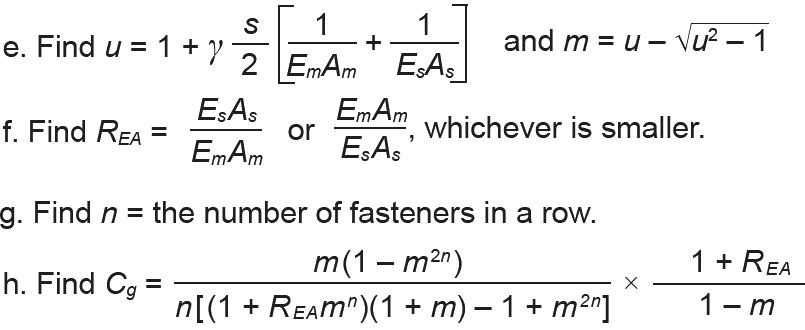
3. Cg = 1.0 for dowel-type fasteners with diameter, D < 0.25 in. Other values for Cg can be determined exactly (for fastener diameters greater than 0.25 in. and less than or equal to 1.0 in.) based on the following method:
a. Find the bolt or lag screw diameter, D; then find the so-called load/slip modulus, γ, as follows:
γ γ = 180,000(D1.5) for dowel-type fasteners in wood-wood connection; γ = 270,000(D1.5) for dowel-type fasteners in wood-metal connection
b. Find s, the spacing (center-to-center) between fasteners in a row;
c. Find Em and Es, the moduli of elasticity (psi) for the main and secondary members, respectively;
d. Find Am and As, the cross-sectional areas (in2) for the main member and for the side member (or the sum of the areas of the side members, if there are more than one), respectively;
4. Applies to dowel-type connectors only.
Table A-3.23: Geometry adjustment factor, CΔ, for wood connectors (bolts and lag screws)
| A. Spacing (in.) between fasteners in a rowa,b,d | ||
|---|---|---|
| Loading direction | Absolute minimum | Minimum for full value |
| Parallel to grain | 3D | 4D |
| Perpendicular to grain | 3D | Whatever is required for attached membersc |
Notes for Part A:
a. Required spacing (in.) is a multiple of the fastener diameter, D (in.).
b. A distance below the absolute minimum is, of course, not permitted — in that case, the geometry factor, CΔ = 0. For any distance equal to or greater than the "minimum for full value," the geometry factor, CΔ = 1.0. For spacing between the two values shown in the table, the geometry factor, CΔ, is taken as the actual spacing divided by the minimum spacing for full value. For example, if the actual spacing between fasteners in a row, where the load was parallel to grain, is 3.5D, the geometry factor, CΔ = 3.5D/(4D) = 0.875. If the spacing in this case equaled the absolute minimum of 3D, the geometry factor, CΔ = 3D/(4D) = 0.75.
c. For fasteners in a row, where the loading is perpendicular to grain, the minimum spacing necessary to obtain the full value of the geometry factor, i.e., CΔ = 1.0, is based on meeting the requirements for the member to which it is attached — i.e., the member whose load is parallel to grain — as long as this distance is no less than the absolute minimum value of 3D (assuming that both members in the connection are not oriented so that the load is perpendicular to grain).
d. See general notes below.
| B. Spacing (in.) between rows of fastenersa,b,d | ||
|---|---|---|
| Loading direction | Condition | Minimum spacing |
| Parallel to grain | All conditions | 1.5D |
| Perpendicular to grainc | l/D ≤ 2 2 < l/D < 6 l/D ≥ 6 |
2.5D (5l + 10D)/8 5D |
Notes for Part B:
a. Required spacing (in.) is a multiple of the fastener diameter, D (in.).
b. Where the minimum spacing between rows of fasteners is met, the geometry factor, CΔ = 1.0. Otherwise, where the spacing is below the minimum allowed, the connection is not permitted — i.e., CΔ = 0. Interestingly, the maximum spacing between rows of fasteners is also limited in the following way: a 5 in. maximum limit is placed on the spacing between the outer rows of fasteners, in cases where the rows are parallel to the grain of the wood. This reduces the possibility of splitting as the wood member shrinks or expands (due to changes in its moisture content) perpendicular to the grain, while the bolts are fixed in place by a connecting member.
c. The fastener length, l (in.), is defined as the length of the fastener that is actually embedded within either the main member (the dowel bearing length — see Appendix Table A-3.27), or the total length within one or more secondary members, whichever is smaller. D is the fastener diameter (in.).
d. See general notes below.
| C. End distance (in.)a,b,c | ||
|---|---|---|
| Loading direction | Absolute minimum | Minimum for full value |
Parallel to grain:
Tension — softwood Tension — hardwood |
2D 3.5D 2.5D | 4D 7D 5D |
| Perpendicular to grain | 2D | 4D |
Notes for Part C:
a. Required end distance (in.) is a multiple of the fastener diameter, D (in.).
b. A distance below the absolute minimum is, of course, not permitted — in that case, the geometry factor, CΔ = 0; for any distance equal to or greater than the "minimum for full value," the geometry factor, CΔ = 1.0. For end distances between the two values shown in the table, the geometry factor, CΔ, is taken as the actual end distance divided by the minimum distance for full value. For example, if the end distance of a fastener loaded parallel to grain in compression is 3D, the geometry factor, CΔ = 3D/(4D) = 0.75. If the end distance in this case equaled the absolute minimum of 2D, the geometry factor, CΔ = 2D/(4D) = 0.50.
c. See general notes below.
| D. Edge distance (in.)a,b,d,e | ||
|---|---|---|
| Loading direction | Condition1 | Minimum Edge Distance |
Parallel to grain |
l/D ≤ 6 l/D > 6 |
1.5D the greater of 1.5D or 1.2 spacing between rows |
| Perpendicular to grainc | loaded edge unloaded edge |
4D 1.5D |
Notes for Part D:
a. Required edge distance (in.) is a multiple of the fastener diameter, D (in.).
b. Where the loading direction is parallel to grain, let l be the fastener length that is actually embedded within either the main member (the dowel bearing length — see Appendix Table A-3.19), or the total length within one or more secondary members, whichever is smaller. D is the bolt or lag screw diameter.
c. Loads should not be suspended in such a way that fasteners are stressing the wood members perpendicular to grain where such fasteners are inserted below the neutral axis (that is, in the tension region) of a single beam.
d. Where the minimum edge distance is met, the geometry factor, CΔ = 1.0. Otherwise, the connection is not permitted — i.e., CΔ = 0.
e. See general notes below.
| E. Spacing and end-edge distances for loading parallel and perpendicular to grain | |
|---|---|
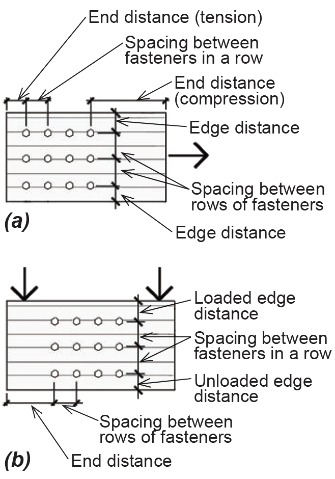 |
End distance is measured parallel to grain at the end of the member. Where the load is also parallel to grain, a distinction is made between the two member ends — one of which is in tension (that is, where the fastener is bearing towards the member end) and one of which is in compression (where the fastener is bearing away from the member end) |
| Edge distance is measured perpendicular to grain, for load parallel to grain | |
| Loaded edge distance is measured perpendicular to grain, for load perpendicular to grain; it refers to the edge that is "pushing" on the fasteners, i.e., the edge where the fasteners are pushing against the member edge | |
| Unloaded edge distance is measured perpendicular to grain, for load perpendicular to grain; it refers to the opposite edge that isn't loaded, that is, the edge where the fasteners are not pushing against the member edge | |
| Both spacing between fasteners in a row, and spacing between rows of fasteners, are self-evident, requiring only that a "row of fasteners" is clearly understood as being parallel to the direction of load, and having no necessary relationship to the direction of grain in the wood members | |
General notes for Table A-3.23:
1. The geometry factor for any connection is taken as the smallest single value computed for any fastener in the connection, based on any of the criteria listed in Appendix Table A-3.23 parts A, B, C, or D, i.e., for both spacing requirements as well as for end and edge distance. All such required spacing and distances are computed as multiples of the fastener diameter, D, for all wood fasteners comprising the connection; but only the smallest geometry factor found within the entire connection is applied to the connection design.
2. CΔ = 1.0 for "end distance" and "spacing between fasteners in a row" when minimum conditions for the full value are met. There are also smaller allowable lengths for these parameters (although subject to an absolute minimum) which, while permitted, reduce the geometry factor to a value less than 1.0.
3. A fastener row refers to a minimum of two fasteners in a line parallel to the direction of the load, whether or not it is parallel or perpendicular to the direction of the grain of wood. On the other hand, end and edge distance are measured parallel and perpendicular, respectively, to the direction of grain, not load, as shown in Appendix Table A-3.23, part E.
4. Applies to dowel-type connectors only, and only when the fastener diameter, D ≥ 1/4 in. Otherwise, CΔ = 1.0.
Table A-3.24: Toe-nail adjustment factor, Ctn, for nails1
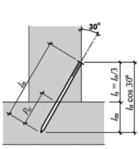 |
Diagram | Direction of Applied Force | Ctn |
|---|---|---|---|
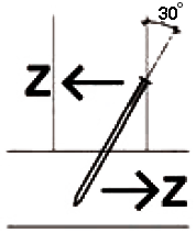 |
For lateral design values, Z, bearing lengths are as follows: • ln main member: lm = ln cos 30° – ln / 3 • In side member: ls = ln / 3 where ln = length of nail |
0.83 | |
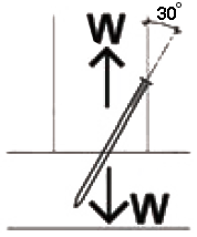 |
For withdrawal design values, W, depth of penetration, pw is actual length of nail in main member. | 0.67 |
Note:
1. Toe-nailing values are based on two assumptions:
a. That the nail is driven at an angle of approximately 30° to the face of the side member.
b. That the nail insertion point is 1/3 of the nail length (ln / 3) above the end of the side member.
Table A-3.25: Temperature factor, Ct, for wood fasteners
| Temperature, T, (°F) | Ct (used dry) | Ct (used wet) |
|---|---|---|
| T ≤ 100°F | 1.0 | 1.0 |
| 100°F < T ≤ 125°F | 0.8 | 0.7 |
| 125°F < T ≤ 150°F | 0.7 | 0.5 |
Table A-3.26: Lateral design value, Z (lb) for bolts: single-shear connections, with 1-1/2 in. side member thickness, both members same species (or same specific gravity)1
| A. Designation for single-shear lateral design values according to direction of grain2 |
|---|
 |
| B. 1-1/2 in. main member thickness | |||||||||
|---|---|---|---|---|---|---|---|---|---|
| Species or Species Combination | 1/2 in. diameter Bolts | 3/4 in. diameter Bolts | 1 in. diameter Bolts | ||||||
| Zpar | Zs-per | Zm-per | Zpar | Zs-per | Zm-per | Zpar | Zs-per | Zm-per | |
| Douglas Fir-Larch | 480 | 300 | 300 | 720 | 420 | 420 | 970 | 530 | 530 |
| Douglas Fir-Larch (North) | 470 | 290 | 290 | 710 | 400 | 400 | 950 | 510 | 510 |
| Douglas Fir-South | 440 | 270 | 270 | 670 | 380 | 380 | 890 | 480 | 480 |
| Hem-Fir | 410 | 250 | 250 | 620 | 350 | 350 | 830 | 440 | 440 |
| Hem-Fir (North) | 440 | 270 | 270 | 670 | 380 | 380 | 890 | 480 | 480 |
| Spruce-Pine-Fir | 410 | 240 | 240 | 610 | 340 | 340 | 810 | 430 | 430 |
| Spruce-Pine-Fir (South) | 350 | 200 | 200 | 520 | 280 | 280 | 700 | 360 | 360 |
| Southern Pine | 530 | 330 | 330 | 800 | 460 | 460 | 1060 | 580 | 580 |
| C. 3-1/2 in. main member thickness | |||||||||
|---|---|---|---|---|---|---|---|---|---|
| Species or Species Combination | 1/2 in. diameter Bolts | 3/4 in. diameter Bolts | 1 in. diameter Bolts | ||||||
| Zpar | Zs-per | Zm-per | Zpar | Zs-per | Zm-per | Zpar | Zs-per | Zm-per | |
| Douglas Fir-Larch | 610 | 370 | 430 | 1200 | 590 | 610 | 1830 | 680 | 740 |
| Douglas Fir-Larch (North) | 610 | 360 | 420 | 1190 | 560 | 490 | 1790 | 650 | 710 |
| Douglas Fir-South | 580 | 340 | 400 | 1140 | 520 | 550 | 1680 | 600 | 660 |
| Hem-Fir | 550 | 320 | 380 | 1100 | 460 | 500 | 1570 | 540 | 600 |
| Hem-Fir (North) | 580 | 340 | 400 | 1140 | 520 | 550 | 1680 | 600 | 660 |
| Spruce-Pine-Fir | 540 | 320 | 370 | 1080 | 450 | 480 | 1530 | 530 | 590 |
| Spruce-Pine-Fir (South) | 490 | 280 | 300 | 990 | 360 | 400 | 1320 | 420 | 480 |
| Southern Pine | 660 | 400 | 470 | 1270 | 660 | 690 | 2010 | 770 | 830 |
| D. 5-1/2 in. main member thickness | |||||||||
|---|---|---|---|---|---|---|---|---|---|
| Species or Species Combination | 5/8 in. diameter Bolts | 3/4 in. diameter Bolts | 1 in. diameter Bolts | ||||||
| Zpar | Zs-per | Zm-per | Zpar | Zs-per | Zm-per | Zpar | Zs-per | Zm-per | |
| Douglas Fir-Larch | 610 | 370 | 430 | 1200 | 590 | 790 | 2050 | 680 | 1060 |
| Douglas Fir-Larch (North) | 610 | 360 | 420 | 1190 | 560 | 780 | 2030 | 650 | 1010 |
| Douglas Fir-South | 580 | 340 | 400 | 1140 | 520 | 740 | 1930 | 600 | 940 |
| Hem-Fir | 550 | 320 | 380 | 1100 | 460 | 700 | 1800 | 540 | 860 |
| Hem-Fir (North) | 580 | 340 | 400 | 1140 | 520 | 740 | 1930 | 600 | 940 |
| Spruce-Pine-Fir | 540 | 320 | 370 | 1080 | 450 | 690 | 1760 | 530 | 830 |
| Spruce-Pine-Fir (South) | 490 | 280 | 330 | 990 | 360 | 570 | 1520 | 420 | 680 |
| Southern Pine | 660 | 400 | 470 | 1270 | 660 | 850 | 2150 | 770 | 1190 |
Notes:
1. Member thickness is measured parallel to the axis of the fastener.
2. Designations for lateral design values are as illustrated: (a) Zpar for both members with direction of grain parallel to load; (b) Zs-per for side member with grain perpendicular to load and main member with grain parallel to load; and (c) Zm-per for main member with grain perpendicular to load and side member with grain parallel to load. A fourth possibility, with both members having grain perpendicular to the direction of load, is rarely encountered and not included here. The official designations also shown below the illustrations contain "parallel" and "perpendicular" symbols instead of the abbreviations, "par" and "per" used in these tables and text.
Table A-3.27: Lateral design value, Z (lb) for bolts: double-shear connections, with 1-1/2 in. side member thickness, both members same species (or same specific gravity)1
| A. Designation for double-shear lateral design values according to direction of grain2 |
|---|
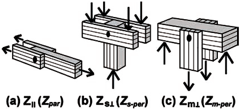 |
| B. 1-1/2 in. main member thickness | |||||||||
|---|---|---|---|---|---|---|---|---|---|
| Species or Species Combination | 1/2 in. diameter Bolts | 3/4 in. diameter Bolts | 1 in. diameter Bolts | ||||||
| Zpar | Zs-per | Zm-per | Zpar | Zs-per | Zm-per | Zpar | Zs-per | Zm-per | |
| Douglas Fir-Larch | 1050 | 730 | 470 | 1580 | 1170 | 590 | 2100 | 1350 | 680 |
| Douglas Fir-Larch (North) | 1030 | 720 | 460 | 1550 | 1130 | 560 | 2060 | 1290 | 650 |
| Douglas Fir-South | 970 | 680 | 420 | 1450 | 1040 | 520 | 1930 | 1200 | 600 |
| Hem-Fir | 900 | 650 | 380 | 1350 | 920 | 460 | 1800 | 1080 | 540 |
| Hem-Fir (North) | 970 | 680 | 420 | 1450 | 1040 | 520 | 1930 | 1200 | 600 |
| Spruce-Pine-Fir | 880 | 640 | 370 | 1320 | 900 | 450 | 1760 | 1050 | 530 |
| Spruce-Pine-Fir (South) | 760 | 560 | 290 | 1140 | 720 | 360 | 1520 | 840 | 420 |
| Southern Pine | 1150 | 800 | 550 | 1730 | 1330 | 660 | 2310 | 1530 | 770 |
| C. 3-1/2 in. main member thickness | |||||||||
|---|---|---|---|---|---|---|---|---|---|
| Species or Species Combination | 1/2 in. diameter Bolts | 3/4 in. diameter Bolts | 1 in. diameter Bolts | ||||||
| Zpar | Zs-per | Zm-per | Zpar | Zs-per | Zm-per | Zpar | Zs-per | Zm-per | |
| Douglas Fir-Larch | 1230 | 730 | 860 | 2400 | 1170 | 1370 | 4090 | 1350 | 1580 |
| Douglas Fir-Larch (North) | 1210 | 720 | 850 | 2380 | 1130 | 1310 | 4050 | 1290 | 1510 |
| Douglas Fir-South | 1160 | 680 | 810 | 2280 | 1040 | 1210 | 3860 | 1200 | 1400 |
| Hem-Fir | 1100 | 650 | 760 | 2190 | 920 | 1080 | 3600 | 1080 | 1260 |
| Hem-Fir (North) | 1160 | 680 | 810 | 2280 | 1040 | 1210 | 3860 | 1200 | 1400 |
| Spruce-Pine-Fir | 1080 | 640 | 740 | 2160 | 900 | 1050 | 3530 | 1050 | 1230 |
| Spruce-Pine-Fir (South) | 980 | 560 | 660 | 1990 | 720 | 840 | 3040 | 840 | 980 |
| Southern Pine | 1320 | 800 | 940 | 2550 | 1330 | 1550 | 4310 | 1530 | 1790 |
| D. 5-1/2 in. main member thickness | |||||||||
|---|---|---|---|---|---|---|---|---|---|
| Species or Species Combination | 5/8 in. diameter Bolts | 3/4 in. diameter Bolts | 1 in. diameter Bolts | ||||||
| Zpar | Zs-per | Zm-per | Zpar | Zs-per | Zm-per | Zpar | Zs-per | Zm-per | |
| Douglas Fir-Larch | 1760 | 1040 | 1190 | 2400 | 1170 | 1580 | 4090 | 1350 | 2480 |
| Douglas Fir-Larch (North) | 1740 | 1030 | 1170 | 2380 | 1130 | 1550 | 4050 | 1290 | 2370 |
| Douglas Fir-South | 1660 | 940 | 1110 | 2280 | 1040 | 1480 | 3860 | 1200 | 2200 |
| Hem-Fir | 1590 | 840 | 1050 | 2190 | 920 | 1400 | 3600 | 1080 | 1980 |
| Hem-Fir (North) | 1660 | 940 | 1110 | 2280 | 1040 | 1480 | 3860 | 1200 | 2200 |
| Spruce-Pine-Fir | 1570 | 830 | 1040 | 2160 | 900 | 1380 | 3530 | 1050 | 1930 |
| Spruce-Pine-Fir (South) | 1430 | 660 | 920 | 1990 | 720 | 1230 | 3040 | 840 | 1540 |
| Southern Pine | 1870 | 1130 | 1290 | 2550 | 1330 | 1690 | 4310 | 1530 | 2700 |
Notes:
1. Member thickness is measured parallel to the axis of the fastener.
2. Designations for lateral design values are as illustrated: (a) Zpar for both members with direction of grain parallel to load; (b) Zs-per for side member with grain perpendicular to load and main member with grain parallel to load; and (c) Zm-per for main member with grain perpendicular to load and side member with grain parallel to load. A fourth possibility, with both members having grain perpendicular to the direction of load, is rarely encountered and not included here. The official designations also shown below the illustrations contain "parallel" and "perpendicular" symbols instead of the abbreviations, "par" and "per" used in these tables and text.
Table A-3.28: Lateral design value, Z (lb) for bolts: double-shear connections, with two 1/4 in. A36 steel side plates1
| A. Designation for double-shear lateral design values according to direction of grain2 |
|---|
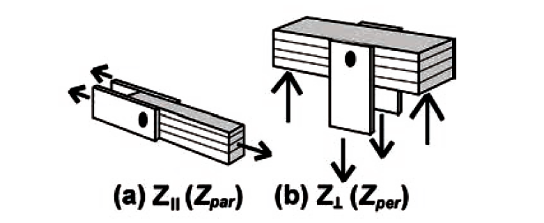 |
| B. 1-1/2 in. main member thickness | ||||||
|---|---|---|---|---|---|---|
| Species or Species Combination | 1/2 in. diameter Bolts | 3/4 in. diameter Bolts | 1 in. diameter Bolts | |||
| Zpar | Zper | Zpar | Zper | Zpar | Zper | |
| Douglas Fir-Larch | 1050 | 470 | 1580 | 590 | 2100 | 680 |
| Douglas Fir-Larch (North) | 1030 | 460 | 1550 | 560 | 2060 | 650 |
| Douglas Fir-South | 970 | 420 | 1450 | 520 | 1930 | 600 |
| Hem-Fir | 900 | 380 | 1350 | 460 | 1800 | 540 |
| Hem-Fir (North) | 970 | 420 | 1450 | 520 | 1930 | 600 |
| Spruce-Pine-Fir | 880 | 370 | 1320 | 450 | 1760 | 530 |
| Spruce-Pine-Fir (South) | 760 | 290 | 1140 | 360 | 1520 | 420 |
| Southern Pine | 1150 | 550 | 1730 | 660 | 2310 | 770 |
| C. 3-1/2 in. main member thickness | ||||||
|---|---|---|---|---|---|---|
| Species or Species Combination | 1/2 in. diameter Bolts | 3/4 in. diameter Bolts | 1 in. diameter Bolts | |||
| Zpar | Zper | Zpar | Zper | Zpar | Zper | |
| Douglas Fir-Larch | 1650 | 1030 | 3340 | 1370 | 4090 | 1580 |
| Douglas Fir-Larch (North) | 1640 | 1010 | 3320 | 1310 | 4810 | 1510 |
| Douglas Fir-South | 1590 | 970 | 3220 | 1210 | 4510 | 1400 |
| Hem-Fir | 1540 | 890 | 3120 | 1080 | 4200 | 1260 |
| Hem-Fir (North) | 1590 | 970 | 3220 | 1210 | 4510 | 1400 |
| Spruce-Pine-Fir | 1530 | 860 | 3080 | 1050 | 4110 | 1230 |
| Spruce-Pine-Fir (South) | 1430 | 680 | 2660 | 840 | 3540 | 980 |
| Southern Pine | 1720 | 1100 | 3480 | 1550 | 5380 | 1790 |
| D. 5-1/2 in. main member thickness | ||||||
|---|---|---|---|---|---|---|
| Species or Species Combination | 5/8 in. diameter Bolts | 3/4 in. diameter Bolts | 1 in. diameter Bolts | |||
| Zpar | Zper | Zpar | Zper | Zpar | Zper | |
| Douglas Fir-Larch | 2410 | 1420 | 3340 | 1890 | 5720 | 2480 |
| Douglas Fir-Larch (North) | 2390 | 1400 | 3320 | 1850 | 5670 | 2370 |
| Douglas Fir-South | 2330 | 1340 | 3220 | 1780 | 5510 | 2200 |
| Hem-Fir | 2260 | 1280 | 3120 | 1690 | 5330 | 1980 |
| Hem-Fir (North) | 2330 | 1340 | 3220 | 1780 | 5510 | 2200 |
| Spruce-Pine-Fir | 2230 | 1270 | 3090 | 1650 | 5280 | 1930 |
| Spruce-Pine-Fir (South) | 2090 | 1140 | 2890 | 1320 | 4930 | 1540 |
| Southern Pine | 2510 | 1510 | 3480 | 2000 | 5960 | 2810 |
Notes:
1. Member thickness is measured parallel to the axis of the fastener.
2. Designations for lateral design values are as illustrated: (a) Zpar for main member with direction of grain parallel to load; and (b) Zper for main member with grain perpendicular to load. The official designations also shown below the illustrations contain "parallel" and "perpendicular" symbols instead of the abbreviations, "par" and "per" used in these tables and text.
Table A-3.29: Lateral design value, Z (lb) for lag screws: single-shear connections, both members same species (or same specific gravity)1,2,3,4
| A. Designation for single-shear lateral design values according to direction of grain2 |
|---|
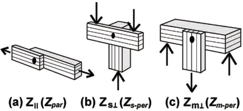 |
| B. 1-1/2 in. side member thickness | |||||||||
|---|---|---|---|---|---|---|---|---|---|
| Species or Species Combination | 1/2 in. diameter Lag Screws | 3/4 in. diameter Lag Screws | 1 in. diameter Lag Screws | ||||||
| Zpar | Zs-per | Zm-per | Zpar | Zs-per | Zm-per | Zpar | Zs-per | Zm-per | |
| Douglas Fir-Larch | 390 | 220 | 270 | 770 | 440 | 510 | 1290 | 530 | 810 |
| Douglas Fir-Larch (North) | 390 | 220 | 260 | 760 | 430 | 510 | 1280 | 500 | 790 |
| Douglas Fir-South | 370 | 210 | 250 | 730 | 400 | 480 | 1230 | 470 | 760 |
| Hem-Fir | 350 | 190 | 240 | 700 | 360 | 450 | 1180 | 420 | 720 |
| Hem-Fir (North) | 370 | 210 | 250 | 730 | 400 | 480 | 1230 | 470 | 760 |
| Spruce-Pine-Fir | 350 | 190 | 240 | 690 | 350 | 440 | 1160 | 410 | 710 |
| Spruce-Pine-Fir (South) | 310 | 160 | 210 | 620 | 280 | 390 | 1070 | 330 | 630 |
| Southern Pine | 410 | 250 | 290 | 830 | 470 | 560 | 1360 | 600 | 870 |
| C. 3-1/2 in. side member thickness | |||||||||
|---|---|---|---|---|---|---|---|---|---|
| Species or Species Combination | 1/2 in. diameter Lag Screws | 3/4 in. diameter Lag Screws | 1 in. diameter Lag Screws | ||||||
| Zpar | Zs-per | Zm-per | Zpar | Zs-per | Zm-per | Zpar | Zs-per | Zm-per | |
| Douglas Fir-Larch | 390 | 270 | 270 | 960 | 600 | 610 | 1740 | 850 | 1060 |
| Douglas Fir-Larch (North) | 390 | 260 | 260 | 950 | 580 | 600 | 1730 | 830 | 1040 |
| Douglas Fir-South | 380 | 250 | 250 | 920 | 550 | 580 | 1670 | 790 | 1000 |
| Hem-Fir | 360 | 240 | 240 | 890 | 500 | 550 | 1610 | 740 | 950 |
| Hem-Fir (North) | 380 | 250 | 250 | 920 | 550 | 580 | 1670 | 790 | 1000 |
| Spruce-Pine-Fir | 360 | 240 | 240 | 880 | 490 | 540 | 1600 | 720 | 940 |
| Spruce-Pine-Fir (South) | 340 | 220 | 220 | 820 | 420 | 490 | 1450 | 630 | 850 |
| Southern Pine | 410 | 290 | 290 | 1010 | 650 | 650 | 1830 | 930 | 1120 |
Notes:
1. Member thickness is measured parallel to the axis of the fastener.
2. Designations for lateral design values are as illustrated: (a) Zpar for both members with direction of grain parallel to load; (b) Zs-per for side member with grain perpendicular to load and main member with grain parallel to load; and (c) Zm-per for main member with grain perpendicular to load and side member with grain parallel to load. A fourth possibility, with both members having grain perpendicular to the direction of load, is rarely encountered and not included here. The official designations also shown below the illustrations contain "parallel" and "perpendicular" symbols instead of the abbreviations, "par" and "per" used in these tables and text.
3. Tabular values are based on full value minimum penetration, p, into main member. For penetration into main member between 4D and 8D, multiply tabular values by p/(8D).
4. The reduced body diameter, Dr, is used in yield limit calculations for these lag screw lateral design values, except in the calculation of the dowel bearing strength for loading perpendicular to grain, Fe-perp, in which case the nominal diameter, D, is used.
Table A-3.30: Lateral design value, Z (lb) for common lails: single-shear connections, both members same species (or same specific gravity)1,2,4
| A. 3/4 in. side member thickness | |||||||||
|---|---|---|---|---|---|---|---|---|---|
| Species or Species Combination | Nail Size (pennyweight) | ||||||||
| 6d | 8d | 10d | 12d | 16d | 20d | 30d | 40d | 50d | |
| Douglas Fir-Larch | 72 | 90 | 105 | 105 | 121 | 138 | 147 | 158 | 162 |
| Douglas Fir-Larch (North) | 71 | 87 | 102 | 102 | 117 | 134 | 143 | 154 | 158 |
| Douglas Fir-South | 65 | 80 | 94 | 94 | 108 | 125 | 133 | 144 | 147 |
| Hem-Fir | 58 | 73 | 85 | 85 | 99 | 114 | 122 | 132 | 136 |
| Hem-Fir (North) | 65 | 80 | 94 | 94 | 108 | 125 | 133 | 144 | 147 |
| Spruce-Pine-Fir | 57 | 70 | 83 | 83 | 96 | 111 | 119 | 129 | 132 |
| Spruce-Pine-Fir (South) | 46 | 58 | 69 | 69 | 80 | 93 | 101 | 110 | 113 |
| Southern Pine | 79 | 104 | 121 | 121 | 138 | 157 | 166 | 178 | 182 |
| B. 1-1/2 in. side member thickness | |||||||||
|---|---|---|---|---|---|---|---|---|---|
| Species or Species Combination | Nail Size (pennyweight) | ||||||||
| 6d | 8d | 10d | 12d | 16d | 20d | 30d | 40d | 50d | |
| Douglas Fir-Larch | — | 397 | 118 | 118 | 141 | 170 | 186 | 205 | 211 |
| Douglas Fir-Larch (North) | — | 395 | 115 | 115 | 138 | 166 | 182 | 201 | 206 |
| Douglas Fir-South | — | 390 | 109 | 109 | 131 | 157 | 172 | 190 | 196 |
| Hem-Fir | — | 384 | 102 | 102 | 122 | 147 | 161 | 178 | 181 |
| Hem-Fir (North) | — | 390 | 109 | 109 | 131 | 157 | 172 | 190 | 196 |
| Spruce-Pine-Fir | — | 382 | 100 | 100 | 120 | 144 | 158 | 172 | 175 |
| Spruce-Pine-Fir (South) | — | 372 | 87 | 87 | 104 | 126 | 131 | 138 | 141 |
| Southern Pine | — | 3106 | 128 | 128 | 154 | 185 | 203 | 224 | 230 |
Notes:
1. Member thickness is measured parallel to the axis of the fastener.
2. Where values are not indicated, nail penetration into main member does not satisfy minimum requirements. Otherwise, except as indicated in Note 3, it is assumed that the minimum penetration of the nail into the main member is equal to 10D (see Appendix Table A-3.19 for notes on penetration).
3. These values must be reduced according to Note 3 in Appendix Table A-3.19, since the penetration falls below the minimum for full value. Nail dimensions can be found in Appendix Table A-3.18.
4. In all cases where yield limit equations are used to compute lateral design values for nails, the dowel bearing length in the main member, lm, is taken as the penetration minus half the length of the tapered tip. Because these tabular lateral design values do not consider this reduced dowel bearing length, they may be slightly non-conservative in some cases (specifically, they may differ in cases where the governing yield limit equation includes the dowel bearing length parameter).
Table A-3.31: Method for determining lateral design value, Z, based on yield limit equations
| For wood-wood or wood-metal connections that do not correspond to the parameters listed in the various Appendix tables, lateral design values may be determined using yield limit equations. 1. Using Appendix Table A-3.11 (specific gravity for wood members), find the specific gravity (G) for wood main and side member(s). 2. Find fastener diameter: use diameter, D, for bolts and nails (unthreaded shanks in contact with members) and reduced body diameter, Dr, for lag screws (in either case, designated as "D" in what follows); 3. Find dowel bearing strength, Fe, for main (Fem) and side (Fes) member(s), in psi units, using the appropriate specific gravity value for each wood member: a. For D > 0.25 in. and wood members loaded parallel to grain, Fe = 11,200G.  c. For D ≤ 0.25 in. and wood members, Fe = 16,600G1.84. d. For A36 steel, Fe = 87,000. e. For A653 GR33 steel (used in certain die-formed galvanized connector plates), Fe = 61,850. 4. Find the dowel bending yield strength, Fyb, in psi units: a. For bolts, use Fyb = 45,000. b. For lag screws with D = 1/4 in., use Fyb = 70,000; with D = 5/16 in., use Fyb = 60,000; for D ≥ 3/8 in., use Fyb = 45,000. c. For nails with 0.099 in. ≤ D ≤ 0.142 in., use Fyb = 100,000; with 0.142 in. < D ≤ 0.177 in., use Fyb = 90,000; with 0.177 in. < D ≤ 0.236 in., use Fyb = 80,000; with 0.236 in. < D ≤ 0.273 in., use Fyb = 70,000; 5. Find the main member and side member dowel bearing lengths, lm and ls, in inches (see Appendix Table A-3.19 for guidance). Even where there are two side members, the side member bearing length only includes the bearing length in a single side member. 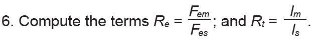 7. Compute the "reduction term," Rd, which varies according to yield mode and fastener diameter, as follows: a. For D ≤ 0.17 in. (i.e., for nails 16d or smaller), Rd = 2.2. b. For 0.17 in. < D < 0.25 in. (i.e., for most nails larger than 16d), Rd = 10D + 0.5. c. For 0.25 in. ≤ D ≤ 1 in. (i.e., for most bolts and lag screws), Rd = 4Kθ (for yield modes Im and Is); Rd = 3.6Kθ (for yield mode II); and Rd = 3.2Kθ (for yield modes IIIm, IIIs, and IV). In these equations, Kθ = 1 + 0.25(θ/90), where θ = the maximum angle (degrees) between the load and the direction of grain for either member: for example, where the load is parallel to the direction of grain in all members, θ = 0 degrees, and Kθ = 1.0; where one or more member's grain is perpendicular to the load, θ = 90°, and Kθ = 1.25. For angles other than 0 or 90°, θ is always measured in such a way that it falls between 0 and 90 (i.e., instead of using θ = 120°, or θ = –45°, use θ = 60° or θ = 45°, respectively). 8. Compute the coefficients k1, k2, and k3, as follows: 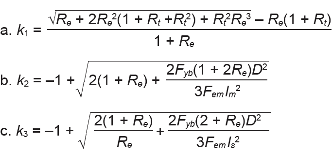 9. Compute the lateral design value, Z, for all applicable yield modes (i.e., for all six modes in single shear, and for all modes except II and IIIm in double shear), and select the smallest value: 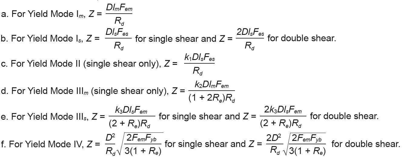 |
Table A-3.32: Withdrawal design value, W, per inch of penetration (lb) for lag screws1,2
| Species or Species Combination | Unthreaded shank diameter, D (in.) | ||||||||
|---|---|---|---|---|---|---|---|---|---|
| 1/4 | 5/16 | 3/8 | 7/16 | 1/2 | 5/8 | 3/4 | 7/8 | 1 | |
| Douglas Fir-Larch | 225 | 266 | 305 | 342 | 378 | 447 | 513 | 576 | 636 |
| Douglas Fir-Larch (North) | 218 | 258 | 296 | 332 | 367 | 434 | 498 | 559 | 617 |
| Douglas Fir-South | 199 | 235 | 269 | 302 | 334 | 395 | 453 | 508 | 562 |
| Hem-Fir | 179 | 212 | 243 | 273 | 302 | 357 | 409 | 459 | 508 |
| Hem-Fir (North) | 199 | 235 | 269 | 302 | 334 | 395 | 453 | 508 | 562 |
| Spruce-Pine-Fir | 173 | 205 | 235 | 264 | 291 | 344 | 395 | 443 | 490 |
| Spruce-Pine-Fir (South) | 137 | 163 | 186 | 209 | 231 | 273 | 313 | 352 | 389 |
| Southern Pine | 260 | 307 | 352 | 395 | 437 | 516 | 592 | 664 | 734 |
Notes:
1. Penetration length for lag screws excludes tapered tip; see Appendix Table A-3.17 for dimensions, and Appendix Table A-3.19 for notes on penetration.
2. Withdrawal design values assume penetration into side grain of wood member, and must be reduced by 75% when inserted into end grain.
Table A-3.33: Withdrawal design value, W, per inch of penetration (lb) for nails1,2
| Species or Species Combination | Nail size (pennyweight) | ||||||||
|---|---|---|---|---|---|---|---|---|---|
| 6d | 8d | 10d | 12d | 16d | 20d | 30d | 40d | 50d | |
| Douglas Fir-Larch | 28 | 32 | 36 | 36 | 40 | 47 | 50 | 55 | 60 |
| Douglas Fir-Larch (North) | 26 | 30 | 34 | 34 | 38 | 45 | 48 | 52 | 57 |
| Douglas Fir-South | 22 | 26 | 29 | 29 | 32 | 38 | 41 | 45 | 48 |
| Hem-Fir | 19 | 22 | 25 | 25 | 27 | 32 | 35 | 38 | 41 |
| Hem-Fir (North) | 22 | 26 | 29 | 29 | 32 | 38 | 41 | 45 | 48 |
| Spruce-Pine-Fir | 18 | 21 | 23 | 23 | 26 | 30 | 33 | 35 | 38 |
| Spruce-Pine-Fir (South) | 12 | 14 | 16 | 16 | 17 | 21 | 22 | 24 | 26 |
| Southern Pine | 35 | 41 | 46 | 46 | 50 | 59 | 64 | 70 | 76 |
Notes:
1. Penetration length for nails includes tapered tip; see Appendix Table A-3.18 for dimensions, and Appendix Table A-3.19 for notes on penetration.
2. Withdrawal design values assume penetration into side grain of wood member. Nails subject to withdrawal are not permitted to be inserted into end grain of wood member.
© 2020 Jonathan Ochshorn; all rights reserved. This section first posted November 15, 2020; last updated December 31, 2020.