Contents | 1. Introduction to structural design | 2. Loads |
Introduction to wood | Material properties | Sectional properties | Design approaches | Construction systems |
Basic tabular values of allowable stresses in tension are shown in Appendix Table A-3.1 for some common species and grades of visually-graded lumber. The allowable stress in tension (parallel to the grain) for timber elements needs to be modified, or adjusted, to account for the variations in material properties discussed earlier in this chapter. The three most important adjustment factors, corresponding to these material properties, are as follows: CM for wood structural elements exposed to wet service conditions; CF for certain cross sections larger or smaller than 2 × 12; and CD for timber elements exposed to a total cumulative "duration of load" different from the time period associated with normal "occupancy" live loads. This adjusted stress, Ft' is computed by multiplying the basic tabular value, Ft , by the appropriate adjustment factors, CD, CM, and CF (see Appendix Table A-3.2). For an explanation of how the duration of load factor, CD, is used, see Appendix Table A-3.10.
The actual tension stress within the structural element is computed by dividing the internal tension force by the cross-sectional area available to resist that force. Where bolt holes are present, the gross area, Ag, of the cross section is reduced by the nominal hole area, as shown in Figure 1.53a. The resulting net area, An, is therefore:
where Dh is the bolt hole diameter, taken somewhat larger than the bolt diameter; and t is the thickness of the cross section. Timber industry specifications recommend that the bolt hole diameter be 1/32 in. to 1/16 in. larger than the bolt diameter; in the examples that follow, a 1/16 in. increase will be assumed. The actual stress, Ft , is therefore:
where no bolt holes are used; and
where bolt holes are present. These equations can be rewritten to solve for the capacity (allowable load), using the adjusted allowable stress, Ft', instead of the actual stress. Where tension elements are nailed rather than bolted, no reduction for nail holes is made; the full gross area is assumed to be available to resist the internal forces:
Where bolt holes are used:
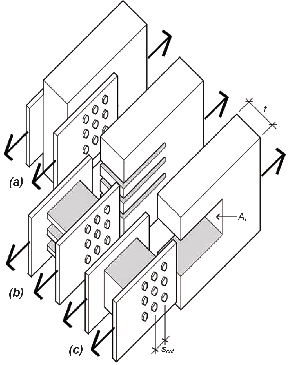
Where wood elements are loaded in tension parallel to grain, another potential mode of failure must be checked where closely-spaced groups of bolts (or lag screws that fully penetrate the main member) are used as fasteners — this phenomenon does not apply to small-diameter nailed connections. As shown in Figure 3.13, the forces transmitted through a fastener group could cause entire "slots" of wood — either within each row of fasteners or for the entire fastener group taken as a whole — to tear out under the load. To prevent failure in the first case ("row tear-out," Figure 3.13b), and in spite of the fact that the forces acting on the element itself are tensile, the external force acting on the connection must be no greater than the total allowable shear force that can be developed on all the potential failure planes along the rows of fasteners. In the second case ("group tear-out," Figure 3.13c), the external force must be no greater than the allowable shear and tension forces that can be safely resisted by the three surfaces forming the boundary failure planes for the group of fasteners as a whole. Of these three surfaces, the resistance of the top and bottom parallel planes, stressed in shear, is equivalent to a single row subjected to row tear-out; the third surface, labeled At in Figure 3.13c, is stressed in tension.

In calculating row and group tear-out, adjusted allowable stresses for shear and tension are used that correspond to the species and grade of the wood elements being checked. The total length of the surface assumed to be resisting shear stress along a given row of fasteners is taken as the smallest distance between fasteners (or between the end of the wood member and the first fastener) multiplied by the number of fasteners in that row. This accounts for the fact that shear stress along the potential failure planes defined by fastener rows is not uniform, but is higher where the area between fasteners along the shear plane is smallest. Additionally, this shear stress is not uniformly distributed between fasteners, but is assumed to step up and down in a triangular pattern, from maximum to zero, so that the average value of shear stress is actually half of its maximum value (corresponding to the average height of such a triangle).
Taking all these caveats into consideration, the allowable maximum force at a connection using bolts or lag screws — where the load is parallel to grain — is limited by the smaller of the following values for row and group tear-out:
a. For row tear-out: multiply the force safely resisted by the two shear planes at each row of fasteners by the number of rows (or, if not all rows of fasteners are the same, add the values for each row computed separately). The force resisted by a single row (arbitrarily called row 1) is equal to:
where n1 = the number of fasteners in row 1; Fv' = the adjusted allowable shear stress for the wood element; scrit = the minimum spacing between fasteners in row 1 (or the distance of the first fastener to the end of the member, if smaller); and t = the member thickness. The force resisted by all fasteners, assuming that all rows are identical, is therefore the force resisted by a single row multiplied by the number of rows, rn, or:
b. For group tear-out: add the shear force resisted at the parallel planes defined by the top and bottom fastener rows (in typical cases where the top and bottom fastener rows have the same geometry, this is equal to the value of Z'RT-1 computed above for single row tear-out; otherwise, add Z'RT-1 /2 for the top and bottom rows) plus the tension force resisted by the plane surface joining, and perpendicular to, these shear planes. For At representing the area subjected to tension stress between the top and bottom rows of fasteners (see Figure 3.13c), and Ft' being the adjusted allowable tensile stress for the wood, the force resisted, in terms of group tear-out, is:
These limitations based on row and group tear-out are summarized in Appendix Table A-3.14.
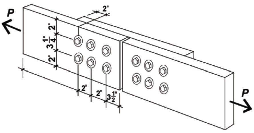
Problem definition. Find the maximum load that can be applied to a 2 × 8 tension element connected with six 1/2 in. diameter bolts. The wood used is Hem-Fir No. 1. Assume live, dead, and wind loads only, dry conditions, and spacing as shown in Figure 3.14.

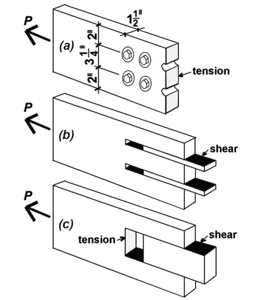
Solution overview. Find gross area and net area; compute adjusted allowable stress; find capacity, P = Ft'An, with the net area as shown in Figure 3.15a. Check row tear-out, based on the shear failure planes shown in Figure 3.15b, and group tear-out, based on the shear and tension failure planes shown in Figure 3.15c. Adjust capacity based on tear-out calculations if necessary.

Problem solution
1. From Appendix Table A-3.12 the cross-sectional area, Ag = 10.875 in2.
2. Use Equation 3.1 to find the net area, An : Notice that even though there are six bolt holes, only two of them are subtracted from the gross area in calculating the net area, since the "failure plane" passes through only two holes. The hole diameter is taken as 1/16 in. larger than the bolt diameter, so Dh = 9/16 = 0.5625 in. Therefore, An = Ag – (no. of holes × Dh × t) = 10.875 – (2 × 0.5625 × 1.5) = 9.19 in2.
3. From Appendix Table A-3.1 find the tabular value of allowable tension stress, Ft = 625 psi.
4. Compute adjusted allowable tension stress:
a. From Appendix Table A-3.2, find adjustments to tabular value: CD = 1.6; CM = 1.0; CF = 1.2.
b. Ft' = FtCDCMCF = 625(1.6)(1.0)(1.2) = 1200 psi.
5. Using Equation 3.5, find capacity (allowable load) based on failure through the net area: P = Ft'An = 1200 × 9.19 = 11,028 lb.
6. From Appendix Table A-3.14, check capacity based on row and group tear-out, since the orientation of the load is parallel to grain and the member is in tension. The adjusted allowable stress in shear is found from Appendix Tables A-3.7 and A-3.8: Fv = 150 psi and the relevant adjustments are for wet service (CM = 1.0) and duration of load (CD = 1.6), so Fv' = 150(1.0)(1.6) = 240 psi. The adjusted allowable tension stress is as found above: Ft' = 1,200 psi. Other parameters needed for this step are as follows: the number of rows, rn = 2; the number of fasteners in a typical row, n1 = 3; the area subjected to tension stress (measured between the top and bottom rows of fasteners), At = (3.25)(1.5) = 4.875 in2; the minimum spacing between fasteners (or the end distance, if smaller), scrit = 2 in.; and the member thickness, t = 1.5 in. The capacities based on row and group tear-out can now be determined:
a. Z'RT = rnn1(Fv')scrit(t) = (2)(3)(240)(2)(1.5) = 4320 lb.
b. Z'GT = n1(Fv' )scrit(t) + Ft'At = (3)(240)(2)(1.5) + (1200)(4.875) = 8010 lb.
Because the smaller of these two values (4320 lb) is smaller than the capacity found in step 4, row tear-out governs the connection design, and the total adjusted connection capacity, P = 4320 lb.
7. Conclusion: the capacity of the 2 × 8 tension element, P = 4320 lb. The capacity of the bolts themselves has not been checked; the design and analysis of such fasteners is discussed later in this chapter.
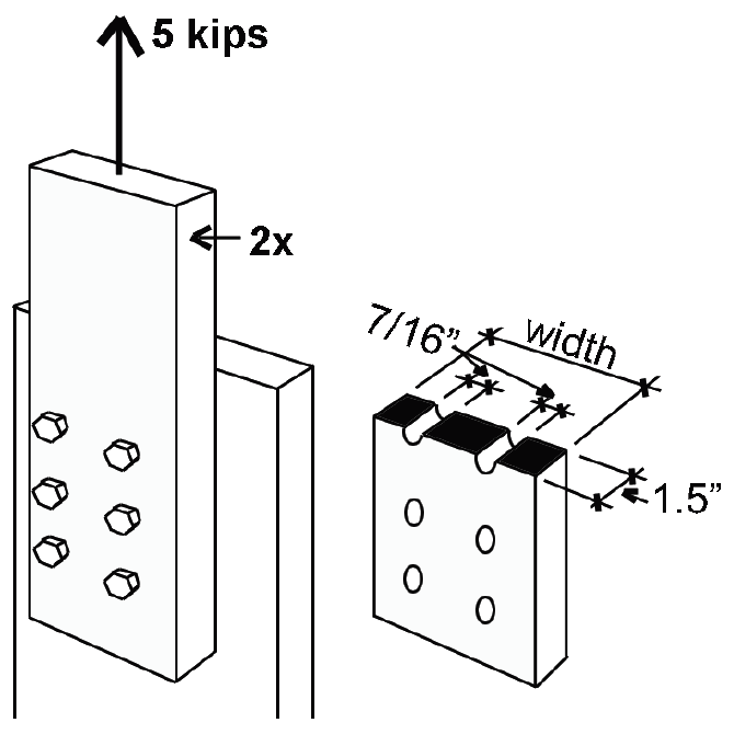
Problem definition. Find an appropriate 2 × cross section (Hem-Fir No. 2) to support a tensile load of 5 kips consisting only of live and dead loads in normal proportions. Use two lines of three 3/8 in. diameter bolts, as shown in Figure 3.16, to connect the wood element to another part of the structure. The bolt hole diameter = bolt diameter + 1/16 in. = 7/16 in. = 0.4375 in.

Solution overview. Compute provisional adjusted allowable stress; find required net area; find required gross area; select provisional cross section; check cross section by finding adjusted allowable stress, required net area, and required gross area. Check row and group tear-out.
Problem solution
1. From Appendix Table A-3.1, find the tabular value of the allowable tension stress, Ft = 525 psi (use "dimension lumber" for 2× element).
2. Compute provisional adjusted allowable tension stress:
a. From Appendix Table A-3.2 find adjustments to tabular value: CD = 1.0; CM = 1.0; assume CF = 1.0 (the actual value is unknown at this time).
b. Ft' = FtCDCMCF = 525(1.0)(1.0)(1.0) = 525 psi.
3. Find required net area, An = load/stress = 5000/525 = 9.52 in2.
4. Using Equation 3.1 (but solving for Ag), and referring to Figure 3.16, find the required gross area, Ag = An + (no. of holes × Dh × t) = 9.52 + (2 × 0.4375 × 1.5) = 10.83 in2.
5. We need a provisional 2× cross section with Ag ≥ 10.83 in2; from Appendix Table A-3.12, select a 2 × 8 with Ag = 10.88 in2. Not only must this cross section be analyzed (using the actual value of CF) but also the next smaller section (since it has a larger value of CF).
Trial 1: 2×8
Because the actual value of the size factor for a 2 × 8, CF = 1.2, is larger than the value initially assumed, the adjusted allowable stress will be higher than assumed, and therefore a 2 × 8 cross section will certainly work. However, it is necessary to analyze (check) the next smaller cross section, since this cross section has an even larger size factor than does the 2 × 8, and so has an even higher adjusted allowable stress.
Trial 2: 2×6
1. From Appendix Table A-3.12 the cross-sectional area of a 2 × 6, Ag = 8.25 in2.
2. Use Equation 3.1 to find the net area, An = Ag – (no. of holes × Dh × t) = 8.25 – 2(0.4375 × 1.5) = 6.94 in2.
3. As before, find the tabular value of allowable tension stress, Ft = 525 psi.
4. Compute adjusted allowable tension stress:
a. From Appendix Table A-3.2, find adjustments to tabular value: CD = 1.0; CM = 1.0; CF = 1.3.
b. Ft' = FtCDCMCF = 525(1.0)(1.0)(1.3) = 682.5 psi.
5. Using Equation 3.5, find capacity (allowable load), P = Ft'An = 682.5 x 6.94 =; 4737 lb. This is insufficient capacity to support a load of 5000 lb: the 2 × 6 is too small. Therefore, the 2 × 8 must be provisionally selected, pending a check of row and group tear-out.
Check row and group tear-out
1. From Appendix Table A-3.14, check capacity based on row and group tear-out, since the orientation of the load is parallel to grain and the member is in tension. The adjusted allowable stress in shear is found from Appendix Tables A-3.7 and A-3.8: Fv = 150 psi and the relevant adjustments are for wet service (CM = 1.0) and duration of load (CD = 1.0), so Fv' = 150(1.0)(1.0) = 150 psi. The adjusted allowable tension stress for the 2 × 8 was never actually determined above; with a size factor, CF = 1.2, it is: Ft' = 525(1.2) = 630 psi. Other parameters needed for this step are as follows: the number of rows, rn = 2; the number of fasteners in a typical row, n1 = 3. Based on the provisional selection of a 2 × 8, let the spacing between bolts in a row, and the distance from the last bolt to the end of the wood element, equal 4 in., and the distance between rows of bolts equal 3-1/2 in. Then, the area subjected to tension stress (measured between the left and right rows of fasteners), At = (3.5)(1.5) = 5.25 in2; the minimum spacing between fasteners (or the end distance, if smaller), scrit = 4 in.; and the member thickness, t = 1.5 in. The capacities based on row and group tear-out can now be determined:
a. Z'RT = rnn1(Fv')scrit(t) = (2)(3)(150)(4)(1.5) = 5400 lb.
b. Z'GT = n1(Fv')scrit(t) + Ft'At = (3)(150)(4)(1.5) + (630)(5.25) = 6007 lb.
2. Conclusion: Because the smaller of the capacities for row and group tear-out (5400 lb) is larger than the actual load of 5000 lb, neither row nor group tear-out governs the connection design, and the 2 × 8 provisionally selected above may be used.
© 2020 Jonathan Ochshorn; all rights reserved. This section first posted November 15, 2020; last updated November 15, 2020.