Jonathan Ochshorn
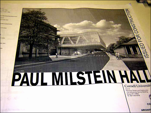
Working drawing cover sheet for Milstein Hall, Cornell University (left); "trailer" for lecture based on the Milstein Hall working drawings (right)
A set of working drawings is like a book in some respects: there is usually a cover and then a table of contents (drawing index). Pages are not numbered sequentially, however; instead, each section (e.g., architectural plans, or sections) has its own sequence of pages. Also, while it is possible to read this "book" from start to finish, the working drawing set is more like a web page with hyperlinks that direct your attention to more detailed information. These "links," or cross-references, most often start with the plans, which then direct you to sections or enlarged plan views. The sections (or plans), in turn direct you to details. These are one-way links, however, so you are often forced to return to the plans to regain your orientation. It is most often difficult to look at a detail, for example, and to understand how it fits into the building without having first found the detail by following indicator marks (links) from plans or sections. Reading working drawings is a nonlinear activity.
Therefore, to understand how to create, or maneuver through, a set of architectural working drawings, it is important to emphasize that the plan is the starting point with most of the other drawings keyed (linked; cross-referenced) from the plan: sections are identified with section indicators; enlarged plan details are identified with dotted rectangles or circles; rooms and partitions are designated so that they can be identified in schedules; elevations are often indicated with special symbols. The "schematic" set of drawings shown below has been designed to show the major types of sheets (i.e., plans, sections, etc.) as well as the primary types of links, or indicators. These drawings do not represent an actual building, and are not designed to be absolutely consistent. A more complete set of guidelines can be found in the National CAD Standard, available here for Cornell students.
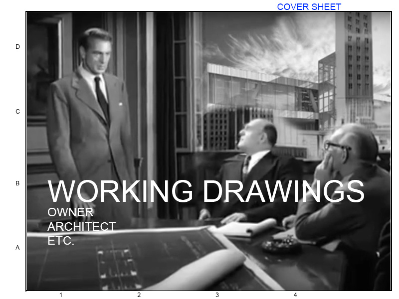
Cover
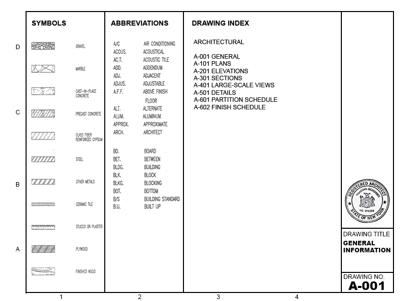
General info
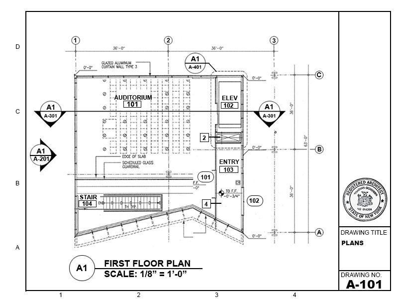
Plans
Elevations
Building sections
Wall sections

Enlarged views
Details
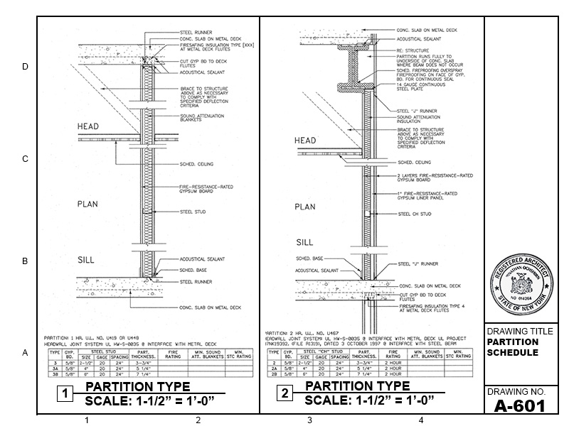
Partition Schedule
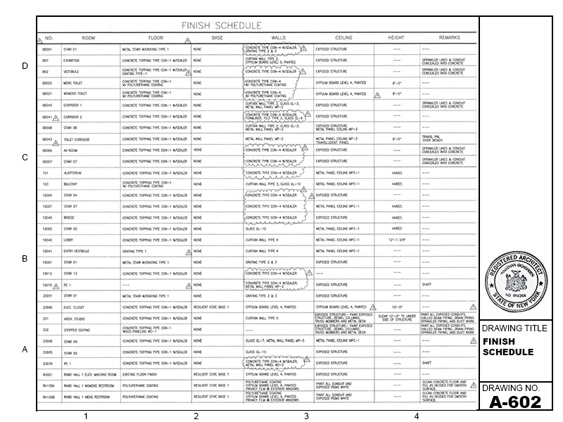
Finish Schedules
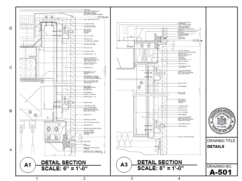
To find a particular detail, e.g., at the intersection of the exterior wall and roof, start with the plan and locate a building section indicator that "cuts" through the building at a point of interest.
This is the building section indicator on the plan sheet, A-101. The horizontal line represents the cut through the building; the arrow shows the direction of view (with everything "behind" the cut line removed).
It can be seen that the section indicator points to Section A1 on sheet A-301. This may be a good time to review what these designations mean. "A1" identifies the module or "drawing block" on the page in which the drawing appears, or the bottom-left module where multiple modules are used for a single drawing. In the schematic sheet represented below, taken from the previous lecture, the shaded area representing a single drawing would be identified as B2. Because Section A1 occupies the entire sheet (i.e., all modules), the designation at the bottom-left, or "A1," is used.
| C1 | C2 | C3 | C4 |
| B1 | B2 | B3 | B4 |
| A1 | A2 | A3 | A4 |
"A-301" is the so-called sheet sequence number, similar to a page number in a book, except that its "chapter" appears as the first letter, i.e., as the appropriate "discipline designator." This discipline designator can be one or two characters, one being more common. A dash is used only with level 1 discipline designators, and not when level 2 discipline designators are used.
| A | - | N | N | N |
"Level 1" discipline designator are single letters, highlighted in the yellow field above; in this case, "A" is for "Architectural."
The sheet type designator follows the hyphen, and consists of one of the following numbers in the first of the three numerical fields:
In other words, the designation, A-301, means that this is part of the "architectural" set, and that the sheet type, "3," refers to "sections." The last two digits represent the page number within the "sections" part of the architectural set: 301 is the first page of the "sections" part; 302 would be the second page; and so on.
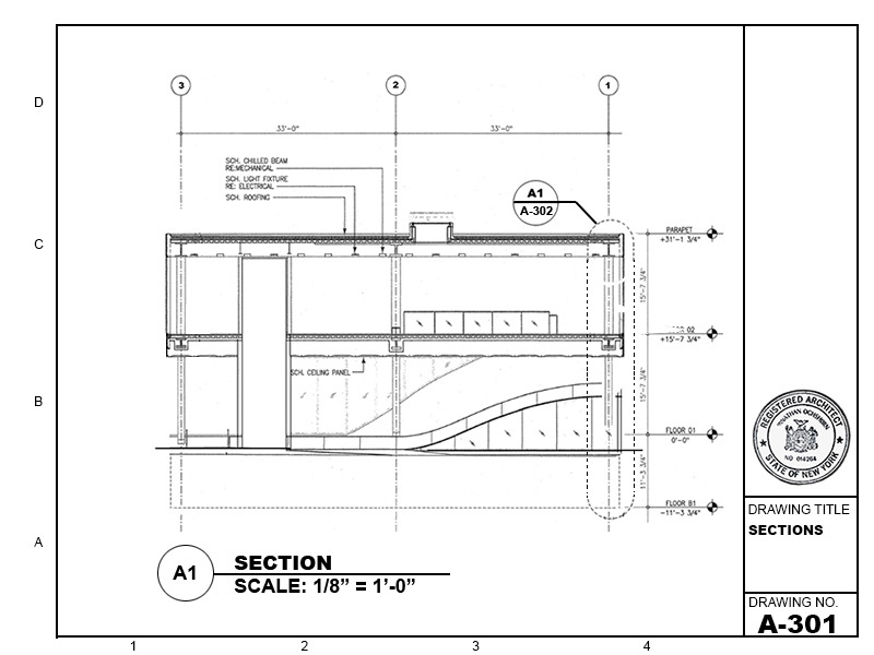
So here is Section A1 on sheet A-301:
This is the building section that was cross-referenced from the plan.
Notice that the actual detail section at the intersection of the wall and roof is not yet cross-referenced from this drawing; instead, we need to first go to a wall section using the detail indicator shown highlighted in yellow. Wall sections are also placed, along with building sections, in the "300" level, in this case, on sheet A-302.
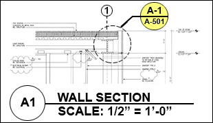
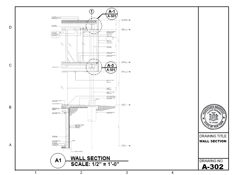
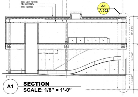
This is a condensed version of the wall section that was cross-referenced from the building section.
At this point, we can finally find a cross-reference to the detail we are interested in: it shows up in the detail indicator highlighted in yellow as drawing A1 on sheet A-501. It should be emphasized that if one came upon this detail by randomly turning pages in the working drawing set, it would not be possible to work backwards in order to find the location of this detail in the actual building — the links, or cross-references, work in one direction only.
There are other useful things linked, or cross-referenced from the plan. In particular, one can find alphanumeric grid designations within column indicators, partition and door type indicators, links to enlarged plan views (of things like stairs, elevators, and bathrooms) and both interior as well as exterior elevations.
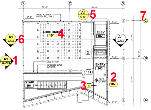
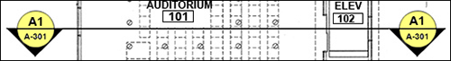
In this plan, one can see (1) exterior elevation indicators; (2) door number indicators; (3) partition type indicators; (4) room number designators; (5) enlarged view indicators; (6) building section indicators; and (7) column indicators.
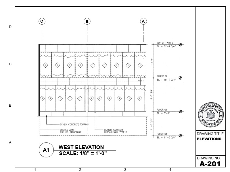
Windows, it should be noted, are typically designated on exterior elevations rather than on plans, as shown in the partial elevation below.
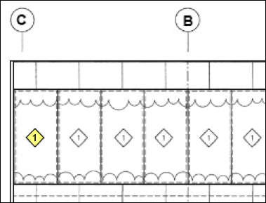
Windows are typically indicated in elevations.
Two tables are shown below, summarizing recommended sheet sizes and line weights. A summary of notation sizes and guidelines follows. All of this is based on information in the National CAD Standard, v.6, available here for Cornell students.
A. Sheet sizeDetermined primarily by plan size; sometimes necessary to subdivide plans, in which case a key plan is needed. | ||||||
| ANSI | ISO | Architectural | ||||
| Mark | Size mm (inches) |
Mark | Size mm (inches) |
Mark | Size mm (inches) |
Typ. applications |
| A | 216x279 (8.5x11) |
A4 | 210x297 (8.3x11.7) |
A | 229x305 (9x12) |
project manual, supplementary dwgs, mock-up sheets |
| B | 279x432 (11x17) |
A3 | 297x420 (11.7x16.5) |
B | 305x457 (12x18) |
"A1" originals, some reduced dwgs, supplementals and mock-ups |
| C | 432x559 (17x22) |
A2 | 420x554 (16.5x22.4) |
C | 457x610 (18x24) |
small projects where sheet size is compatible with plan dimensions |
| D | 559x864 (22x34) |
A1 | 594x841 (23.4x33.1) |
D | 610x914 (24x36) |
government projects; other projects consistent with plan size |
| E | 864x1118 (33x44) |
A0 | 841x1189 (33.1x46.8) |
E | 914x1219 (36x48) |
large projects |
| F | 762x1067 (30x42) |
alternate size, consistent with plan dimensions | ||||
B. Line weights | |
| Typical use of line | Line width (mm) |
| Extra fine detail where the 0.18 mm line just doesn't work | Extra fine 0.13 |
| Material indications, surface marks, hatch lines, and patterns | Fine 0.18 |
| Text (from 3/32" to 3/8"; i.e., 2.5 mm to 10 mm); also dimension lines, leaders, break lines, dotted lines, center lines, grid lines, etc. | Thin 0.25 |
| Text (from 5/32" to 3/8"; i.e, from 4 mm to 10 mm); also object lines, property lines, text, lettering, terminator marks, door and window elevations, etc. | Medium 0.35 |
| Text (from 7/32" to 3/8"; i.e., from 6 mm to 10 mm); also titles, edges of interior and exterior elevations, profiling, cut lines, property lines, drawing block borders, and section cutting plane lines. | Wide 0.50 |
| Text (from 1/2" to 1"; i.e., from 13 mm to 25 mm); also match lines, large titles, title block borders, sheet borders, outlines for schedules, etc. | Extra wide 0.70 |
| Major title underlining and lines that separate portions of the design | XX Wide 1.00 |
| Border sheet outlines and cover sheet line work per ISO 128-20-1996 | XXX Wide 1.40 |
| Border sheet outlines and cover sheet line work | XXXX Wide 2.00 |
Fonts used for notations should have the following characteristics: they should be capitalized, proportional, sans-serif, and non-stylized. In other words, do not use italics, underlining, bold, or other highlighting techniques. Notes should be 2.4 mm (3/32") high capital letters (where hand drawn, the minimum font height increases to 1/8"). Text is black, not gray scaled or colored.
Notes should be written using complete terminology and avoiding, where possible, the use of abbreviations. Where abbreviations are necessary, e.g., to save space in schedules, make sure that the abbreviation chosen is coordinated throughout the drawings and specifications.
Avoid useless and redundant references to specifications such as "PER SPECS" or "REFER TO SPECIFICATIONS." The specifications are already part of the contract documents, whether or not they are mentioned in the drawing notations. Instead, references to specifications should be purposeful, for example, providing an exact reference location within the project manual: "SEE SPECIFICATION SECTION 09 25 13.13."
In the same way, avoid general references to other consultants' drawings such as "REFER TO STRUCTURAL DRAWINGS." Instead, where necessary, refer to a more exact reference location within the drawing set such as: "REFER TO STRUCTURAL FOUNDATION PLAN or REFER TO SHEET S-101."
The National CAD Standard (Cornell students can follow links for free access to v.6)
Architect's Handbook of Professional Practice (Emily's notes) (pdf).
Working Drawings Handbook (pdf), 4th edition
Overview of technical documentation: Lecture notes
Disclaimer: Students are responsible for material presented in class, and required material described on course outline. These notes are provided as a tentative outline of material intended to be presented in lectures only; they may not cover all material, and they may contain information not actually presented. Notes may be updated each year, and may or may not apply to non-current versions of course.
first posted Nov. 15, 2012 | last updated: October 3, 2020
Copyright
2007–2021 J. Ochshorn. All rights reserved. Republishing material on this web site, whether in print or on another web site, in whole or in part, is not permitted without advance permission of the author.