Jonathan Ochshorn
Note: the construction documents are NOT a set of instruction on "how to build the building." In U.S. practice, the contractor retains much responsibility to deal with construction means, methods, techniques, sequences, procedures, site safety, and so on.
AIA Document A201 General Conditions of the Contract for Construction, contains typical conditions which are expanded upon in Division 1 of the Specifications:
Part 1 of other Specification sections include:
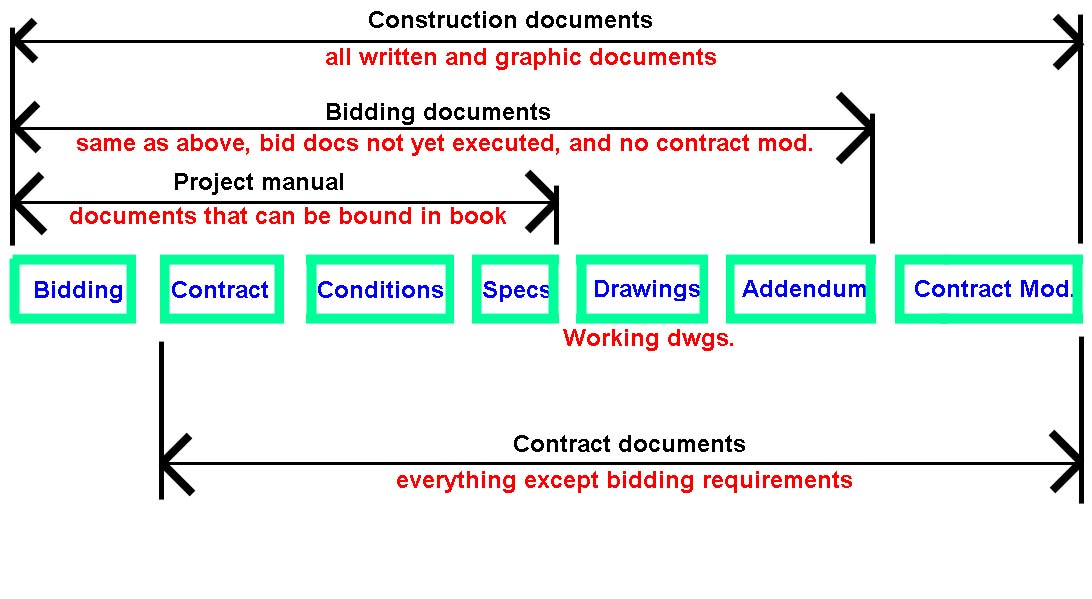
Drawings: quantities, configurations (geometry)
Specifications: qualities, standards of craftsmanship.
Specifications are written in 3 parts:
Section not used.
033100 CONCRETE
Use 4,000 psi concrete with a maximum slump of 4". Contractor is responsible for providing the mix design. Use Grade 60 reinforcing steel (epoxy coated when required). Contractor is responsible for all concrete testing (strength, slump, and air content). Actual type and size of footing and foundation system used will be based on soil borings. Slab on grade floors.
042113 BRICK MASONRY
Brick masonry over metal stud framing and solid masonry where shown. Mortar ASTM C270.
042200 CONCRETE UNIT MASONRY
ASTM C90, normal weight, Type I, concrete masonry units. Mortar ASTM C270. Grout ASTM C476, 2000 psi. Reinforcing ASTM A615, Grade 60.
051200 STRUCTURAL STEEL - GENERAL
Structural steel frame (beams and columns) and miscellaneous members to conform to ASTM A992, 50 ksi. Bolts to conform to either ASTM A307 or A325. Painting to consist of 1-coat of rust-inhibitive primer.
061000 ROUGH CARPENTRY
Wood furring, sheathing, and blocking for built in casework and nailers for the top of all roof-framing members; minimum 5/8-inch thick structural grade plywood for roof sheathing.
062000 FINISH CARPENTRY
Wood veneer finish casework, solid wood and/or plastic laminate counters, in AWI premium quality for the Information Desk, Sales Area, Library, and Staff Office. Solid wood standing and running trim.
072100 BUILDING INSULATION
2-1/2-inch thick (R-11+) extruded polystyrene board perimeter insulation at foundations. R-19 batt insulation for exterior walls. R-38 batt insulation in roofs.
072600 VAPOR RETARDERS
4 mil thick polyethylene under slab on grade and on walls where indicated.
073100 SHINGLES
Mineral fiber cement roof shingles.
074100 METAL ROOFING
2-inch high standing seam, Kynar 500 finished Galvalume metal roofing.
076000 FLASHING AND SHEET METAL
Galvanized sheet metal, painted where exposed.
077200 ROOF ACCESSORIES
Provide continuous metal gravity ridge and fascia ventilators.
079200 JOINT SEALANTS
Use silicone or polyurethane sealants in color to match adjacent surfaces.
081100 METAL DOORS AND FRAMES
Hollow metal doors and frames at toilets, mechanical rooms, and emergency exits.
081400 WOOD DOORS
Provide paneled oak and glass entrance doors with oak frames. On interior, use oak wood veneer solid core wood doors with oak wood frames.
085213 METAL CLAD WOOD WINDOWS
Aluminum clad wood custom windows.
086200 UNIT SKYLIGHTS
Aluminum frame and laminated glass skylight.
087000 HARDWARE
Latch sets, hinges, stops, plates, pulls etc. in oil rubbed and oxidized satin bronze (BHMA 613 or US10B) finish. Use levers on all latch and lock sets, except at service or utility areas use spherical knobs. Master key all locks to the system in use at the park.
088000 GLAZING
Provide 1-inch sealed insulated glass, made up of 1/4-inch thick clear float glass with e2 coating on interior panes of South and East walls. Provide heat mirror glass units on North walls. Use tempered glass where required.
092216 NON-STRUCTURAL METAL FRAMING
Metal stud wall and ceiling framing.
092900 GYPSUM BOARD
Use 5/8" regular gypsum board on designated interior walls and on all ceilings. 5/8" water resistant gypsum board in wet areas. Use cementitious glass mesh mortar units on walls designated to have ceramic tile applied. Use Type X gypsum board on partitions requiring fire rating.
093013 CERAMIC TILE
Ceramic mosaic tile walls and quarry tile floors in Toilets (Public and Staff).
096500 RESILIENT FLOORING
Provide resilient flooring in utility, storage, and mechanical spaces.
096813 TILE CARPETING
Continuous filament, soil repellent, recycled material carpet tile with a pile weight of not less than 36 oz. per square yard in Offices, Exhibits, Multipurpose Room, and Library.
099100 PAINTING
Epoxy coatings in toilet rooms, alkyd enamel semi-gloss paints on scheduled walls and ceilings. Use clear stain on interior and exterior wood trim. Ceilings painted white. Meet state volatile organic compound requirements.
101400 SIGNAGE
Signs for selected rooms.
102113 TOILET COMPARTMENTS
Floor mounted and overhead braced high-density solid polyethylene partitions with self-closing doors with latches and coat hooks.
102813 TOILET ACCESSORIES
Stainless steel (satin finish) recessed accessories including soap dispensers, towel dispensers, waste receptacles, toilet paper holders, grab bars, feminine napkin dispensers and disposals, and framed glass mirrors.
104400 FIRE PROTECTION SPECIALTIES
Manual extinguishing equipment located in accordance with NFPA 10.
107500 FLAGPOLE
Aluminum flagpole located near front entrance walk.
1126000 UNIT KITCHENS
Unit kitchen in Staff Office.
Unlike outline specifications, full specifications have a three-part organization for each Masterformat section, as follows:
These can be extremely detailed, unlike the short summaries typical of outline specifications.
Examples of manufacturers' specifications for their products can be found here, or here, or here. More "generic" spec libraries can be purchased from organizations such the AIA.
Drawing set organization: use discipline designators (e.g., A for architectural) and sheet types (e.g., plans, elevations, sections, large-scale views, details, schedules/diagrams, and 3D representations); use standard formats for sheets (size, layout) and schedules.
An example of a "level 2" discipline designator is "ET" for electrical telecommunications, where the "level 1" discipline designator, "E," is just plain electrical.
In the following descriptive tables, A = alphabetical character and N = numerical character.
| A | A | N | N | N |
| A | A | N | N | N |
| A | A | N | N | N |
| A | - | N | N | N |
| A | A | N | N | N |
| A | - | 1 |
| A | A | N | N | N | - | U | U | U |
Library files are more generic and can be used in various projects.
use masterformat or uniformat system to group such files.
copy and modify, rather than modifying the original library file; rename as appropriate for each project.
Project files are specific to a project, and include such things as building or site models, details, sheets, etc.
For example, a detail file may include plans, elevations, sections, or details; they use the "dot" prior to a suffix, as follows: A-NNN-AN.AAA or A-501-B3.DWG
In this designation, A-501 is the sheet identification, B3 is the detail identification number (referring to the coordinate location on the sheet).
Text files could be such things as general notes, etc.
Database files include the formatting and information needed for schedules and other lists.
Government projects (federal only) are metric and use ANSI official sheet sizes. See chart below:
| ANSI | ISO | Architectural | ||||
| Mark | Size mm (inches) |
Mark | Size mm (inches) |
Mark | Size mm (inches) |
Typ. applications |
| A | 216x279 (8.5x11) |
A4 | 210x297 (8.3x11.7) |
A | 229x305 (9x12) |
project manual, supplementary dwgs, mock-up sheets |
| B | 279x432 (11x17) |
A3 | 297x420 (11.7x16.5) |
B | 305x457 (12x18) |
"A1" originals, some reduced dwgs, supplementals and mock-ups |
| C | 432x559 (17x22) |
A2 | 420x554 (16.5x22.4) |
C | 457x610 (18x24) |
small projects where sheet size is compatible with plan dimensions |
| D | 559x864 (22x34) |
A1 | 594x841 (23.4x33.1) |
D | 610x914 (24x36) |
government projects; other projects consistent with plan size |
| E | 864x1118 (33x44) |
A0 | 841x1189 (33.1x46.8) |
E | 914x1219 (36x48) |
large projects |
| F | 762x1067 (30x42) |
alternate size, consistent with plan dimensions | ||||
Sheet layout:
| C1 | C2 | C3 | C4 |
| B1 | B2 | B3 | B4 |
| A1 | A2 | A3 | A4 |
If a drawing uses more than one module (called a "drawing block"), its designation is taken from the bottom-left module, so the following shaded area representing a drawing would be identified as B2:
| C1 | C2 | C3 | C4 |
| B1 | B2 | B3 | B4 |
| A1 | A2 | A3 | A4 |
BIM is an acronym for "building information modeling," a way to represent a building digitally by creating a parametric model. For example, a "window" can be "attached" to (or "hosted" by) a wall so that when the wall moves, the window goes with it. This "window" also contains actual properties of the window embedded as data, so that things like energy analysis, cost estimating, and specifications can be automatically generated. In general, changes made to one element of the BIM model automatically generate appropriate changes throughout the whole model. Importantly, coordination becomes more systematic: various consultants using the same BIM model can avoid costly errors, e.g., showing mechanical ducts running through structural beams. See this analysis of BIM prepared by Autodesk.
BIM has its own objectives and standards. Here's what Autodesk University says about the relationship between BIM and the National CAD Standard:
"The National Building Information Modeling Standard (NBIMS) doesn't attempt to define graphical standards so the United States National CAD Standard (NCS) remains the standard for the foreseeable future. The NCS still applies because much of the output from BIM is still printed drawings and CAD exports. Which standard applies to what? Where should those transitioning from a CAD to BIM environment look within these standards for guidance? A BIM module is being developed to interconnect the National CAD Standard and the National BIM Standard to address these questions and more. This roundtable discussion gives attendees the opportunity to provide input that shapes a BIM module within the National CAD Standard to interconnect the standards. Attendees also gain knowledge on how to get involved in future development of the standards."
Connecting the National CAD and BIM Standards
Cornell students have access to Revit tutorials (scroll down to bottom).
Disclaimer: Students are responsible for material presented in class, and required material described on course outline. These notes are provided as a tentative outline of material intended to be presented in lectures only; they may not cover all material, and they may contain information not actually presented. Notes may be updated each year, and may or may not apply to non-current versions of course.
first posted Sept. 27, 2012 | last updated: Oct. 6, 2021
Copyright
2007–2020 J. Ochshorn. All rights reserved. Republishing material on this web site, whether in print or on another web site, in whole or in part, is not permitted without advance permission of the author.