Jonathan Ochshorn
Overview: Roofing assemblies consist of two parts:
the substrate (structural frame and deck), that provides a surface for the...
roofing (the actual water barrier that protects the substrate, and everything beneath it).
There are two main categories of roofing:
steep-slope (based on a watershedding, overlapping principle);
low-slope (often incorrectly called "flat;" although it is possible, but unusual, to design a roof that is literally flat: based on watertight, continuous membrane).
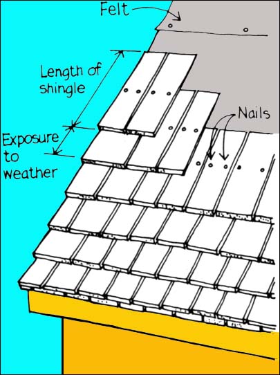
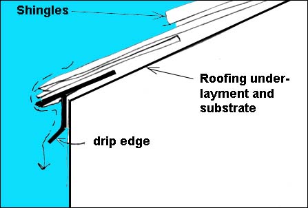
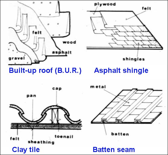
The most common roofing element for steep-slope roofing is the shingle which can be fabricated from many materials, as long as they shed water: wood, asphalt, fiberglass, clay, concrete, and metal are all used. The basic principle is a staggering of the horizontal "courses," and an overlapping of the shingles along the slope. As seen in the image below, the actual shingle length must be somewhat longer than twice the exposure in order to maintain the watershedding capability:
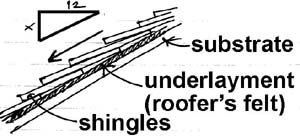
The slope is indicated by the ratio in inches of "rise" to "run;" i.e., x : 12 where x varies from about 4 up to 12 or more (where 12 : 12 is a 45-degree angle). Below about 4 : 12, the roof looses its ability to shed water reliably, and a more rigorous and water-tight underlayment system must be used.
The roof pitch, not commonly used, is the ratio of "rise" to twice the "run," i.e., the pitch is one-half of the slope. A slope of 6:12 is equivalent to a pitch of 6:24 or 3:12.
The underlayment, or roofing felt, provides temporary waterproofing of the exposed substrate during construction as well as a second line of defense after completion. Additionally, it can act as an air barrier, and as a cushion, especially when used with brittle shingles (clay tile, concrete).
 :
:
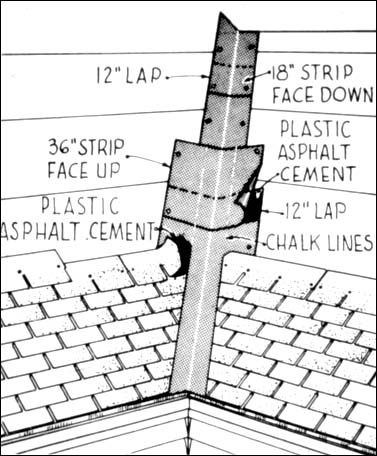
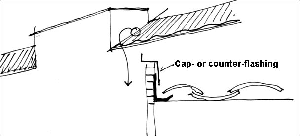
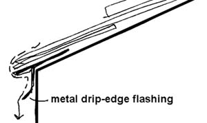
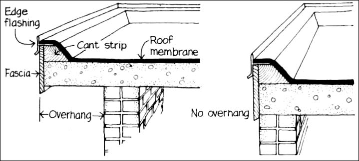
Where two materials intersect, or where the roofing terminates, flashing is used as a transitional device to maintain the continuity of the water protection. Two applications of flashing are:
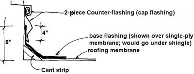
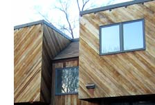
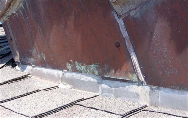
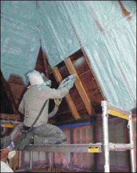
Note that the base flashing, when used with shingles (image at right, Ithaca housing, photo by J. Ochshorn), is typically sheet metal, and may be covered by the shingles and the wall siding; whereas it would be similar to the roofing material in a low-slope context.
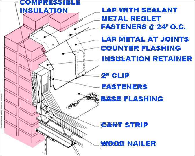
The cant strip is used typically with traditional low-slope roofs (B.U.R.) but is often not required with modern single-ply materials. Its purpose is to ease the transition of the base flashing material from horizontal to vertical, so that it doesn't crack.
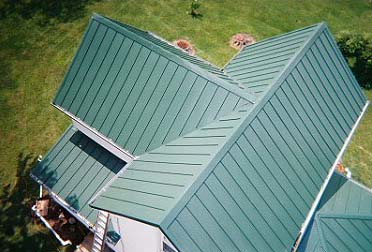
The metal roof shown above is from Indiana Steel Roofing.
When two dissimilar metals are brought into contact with an electrolyte, electric current flows. This is the principle of a battery, and also is the often unintended consequence of using different metals that are exposed to water (which acts as an electrolyte). Where galvanic action is present, one of the metals will corrode (the "anode") as the other gains ions (the "cathode"). The so-called galvanic potential between metals is tabulated in many sources, including Architectural Graphic Standards. Some selected metal combinationss and their galvanic potential (high = avoid direct contact; possible = direct contact is not advisable; and low = in most cases, no problems arise from the metals in contact) are shown below:
Avoid mixing metals within flashing systems; do not use nail or screw materials that differ from the metals they are fastened through: in other words, use aluminum nails with aluminum flashing; copper nails with copper flashing; etc.
Where two metals must be brought into contact in an exterior application (where water is likely to be present), a coating should be applied between the points of contact.
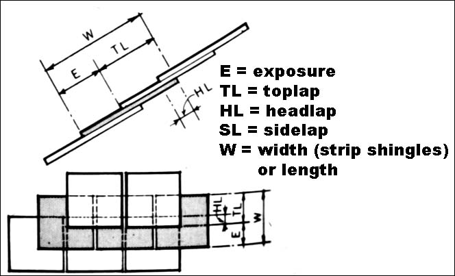
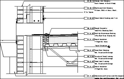
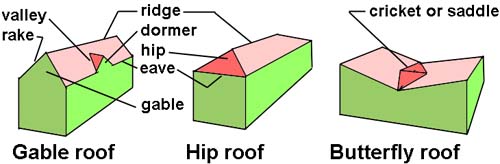
The terms and geometries shown below are commonly encountered in steep-slope roof construction:
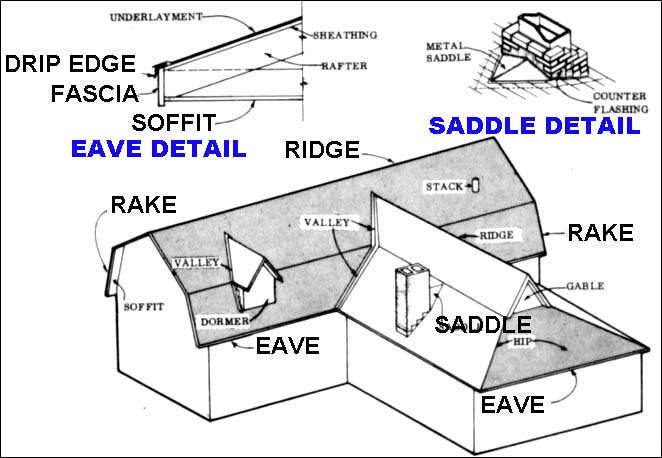
The "soffit" and "fascia" (the underside of a projecting roof is the soffit; the vertical surface where the roof projects beyond the wall surface is the fascia) are shown in the details above. Note that these two terms are also used in other contexts. Also note that a parapet (not shown) is a vertical extension of an exterior wall up beyond the plane of the roof, originally mandated for fire protection, but also useful as a guard rail.
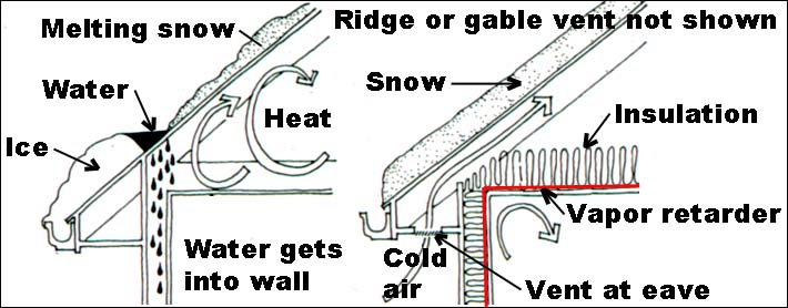
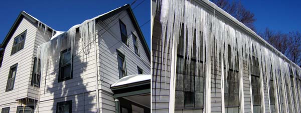
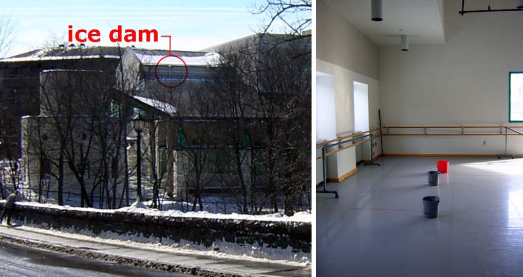
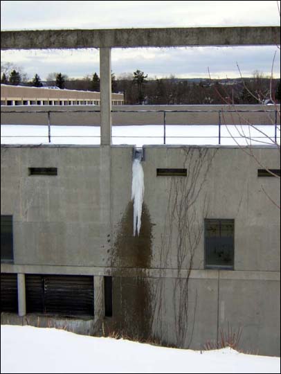
Ice dams occur whenever melting snow on a roof (over a heated or poorly insulated space) freezes upon reaching a roof overhang (over an unheated space). The result can be merely dangerous (icicles posing a hazard to people below) or also damaging to the building itself, in cases the melted water is prevented from draining from the roof by the dam of frozen water (ice) and works its way under shingles and into the building itself.
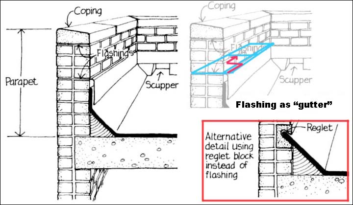
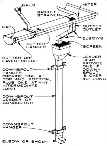
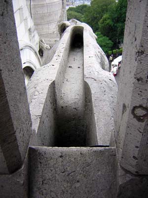
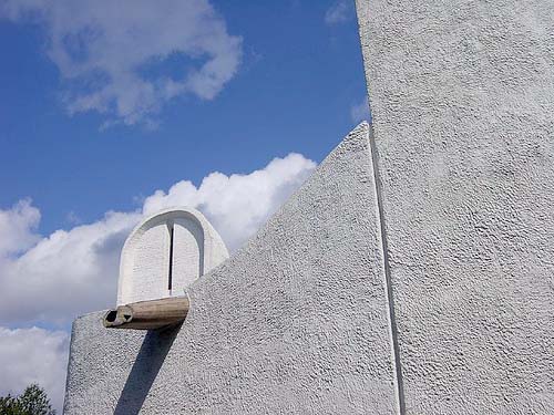
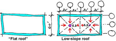
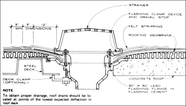
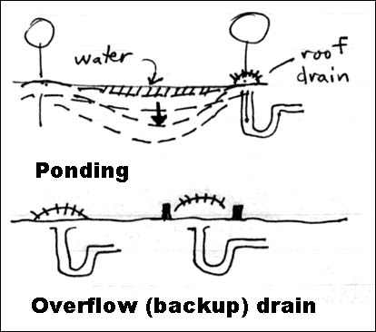
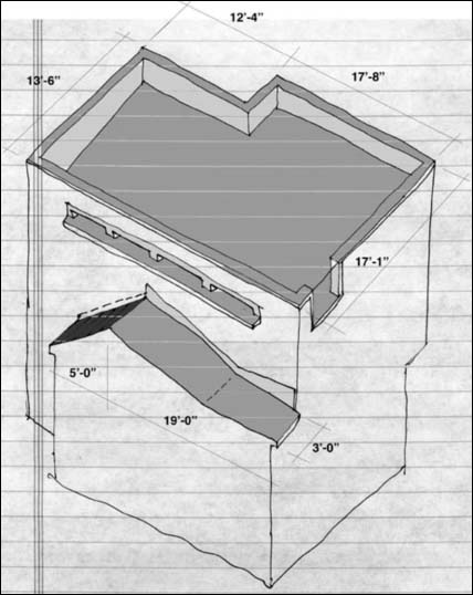
Low-slope roofing may look flat, but except in rare circumstances, it has a minimal slope to eliminate rain water, either over the side (perhaps through a scupper), or internally to a roof drain. The minimum slope, often specified in building codes, is typically 1/4" rise per foot of run, or more. Thus, the roof shown below (assuming a 1/4" slope) has a change of elevation from its high point along the edge to its low point at the two roof drains (marked "R.D.") of 30 x 1/4 = 7.5 inches.
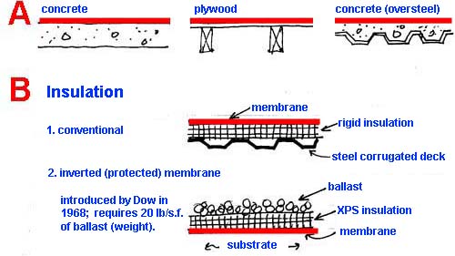
In the inverted membrane roof (protected membrane roof) shown above, the insulation must be able to be in contact with water; the membrane and the insulation are typically loose-laid (unattached) and held in place with gravel or concrete pavers acting as ballast (weight). This is the only roof type that corresponds to the "rules" in Ronald Brand's Architectural Details for Insulated Buildings (see notes from week 11a).
For low-slope membrane-type roofs, there are two main categories:
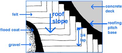
Built-up roofing [B.U.R.]: i.e., the traditional asphaltic or coal-tar based membranes consisting of alternate layers of bitumen over roofing felt.
The bitumen is either based on asphalt (derived from petroleum) or coal tar (bi-product of coal to coke production); the felt strengthens and stabilizes the bitumen and is applied in 3,4, or more layers to produce 3-ply or 4-ply roofs. The top layer is the so-called "flood" coat, often surfaced with aggregate to protect the B.U.R. from UV radiation, heat gain, and pedestrian traffic (e.g., maintenance).
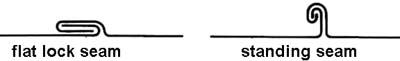
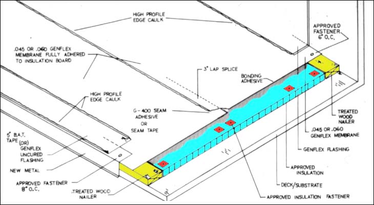
In steel-framed buildings especially, the single-ply membrane is often placed over rigid insulation, which is placed directly over the corrugated steel decking. The video shown in class promoted the use of polyisocyanurate insulation boards, but other insulation materials can also be used as a substrate.
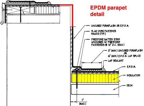
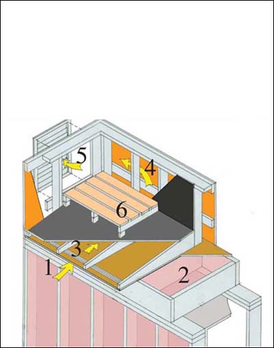
Unlike traditional built-up roofing, many single-ply systems do not require cant strips at 90-degree transitions. A composite EPDM detail based on typical manufacturer's recommended base flashing and parapet details is shown below. See Firestone RubberGard for more information.
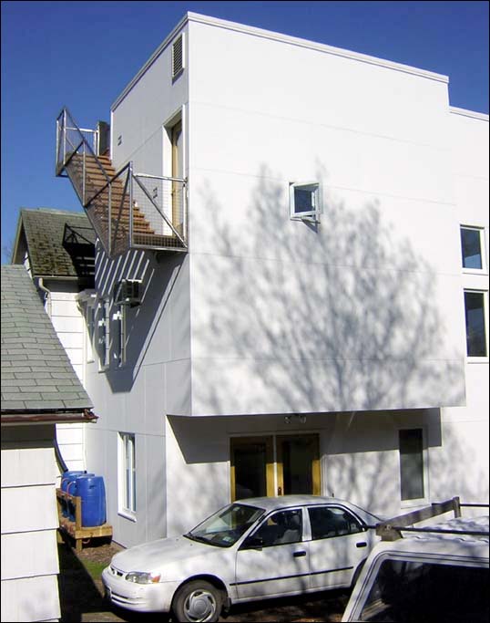
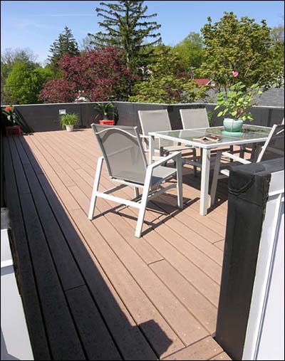
Some images of my own EPDM roofing adventure are shown below. More details can be found here.
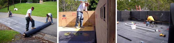
Design-build addition: photos by J. Ochshorn
Whether a roof or some other outdoor surface (plaza, deck, street, courtyard, etc), all nominally "flat" surfaces must actually slope to some sort of drain. Where this is not done — for example, where an absolutely flat plaza or deck is built over a basement space — bad things can happen: see this case study of OMA's Milstein Hall at Cornell University. More commonly, a pattern of drains is placed on the hardscape (or landscape), with a subtle pattern of sloping surfaces, often in the form of inverted pyramids, as in this example at the Physical Sciences Building at Cornell:
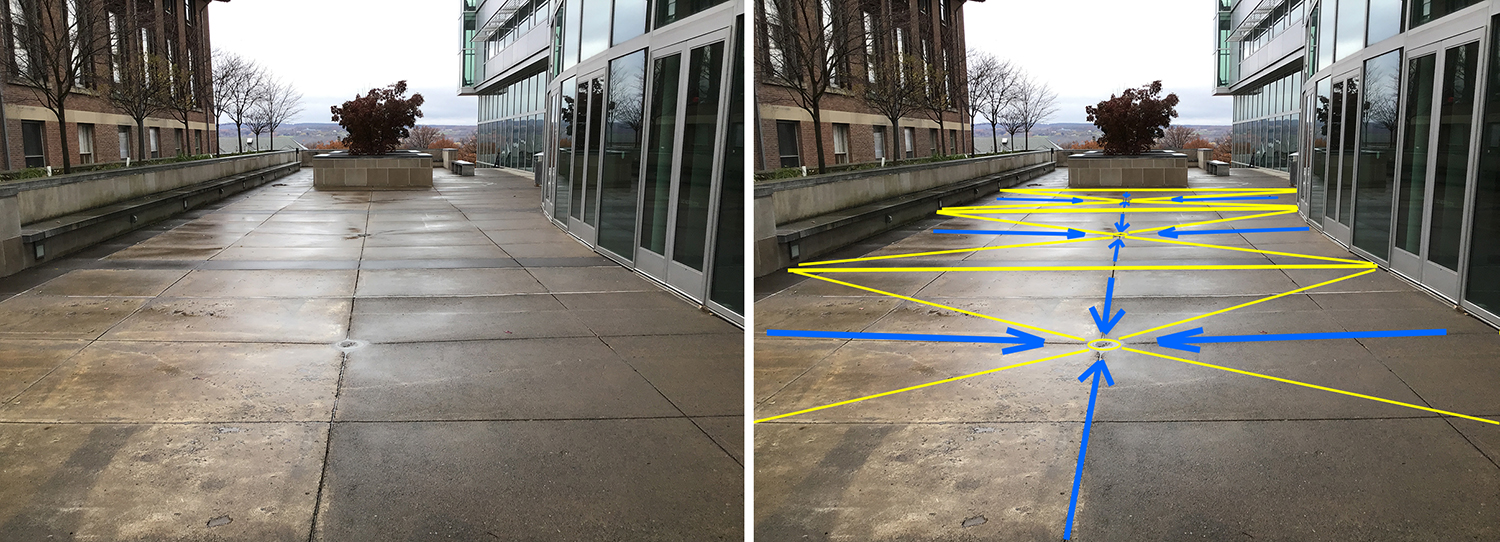
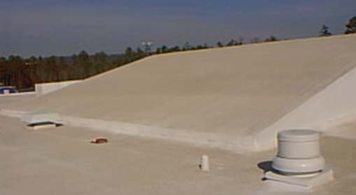
Photo from: NTEC Systems
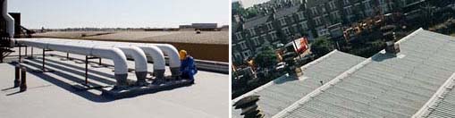
Photo from: Tor Coatings
A variant on the membrane roof, most often accomplished with single-ply membranes, is the so-called "green" roof, in which various landscape products are grown over a series of layered elements, the bottom of which is a single-ply roof membrane, while others include grids to promote drainage, XPS rigid insulation, and a board to block root growth (and thereby protect the roofing membrane). See, for example, this information page from Hydrotech, whose system is shown below:
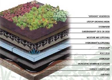
In this system, the roofing membrane is a hot, fluid-applied rubberized asphalt with a minimum 25% recycled content.
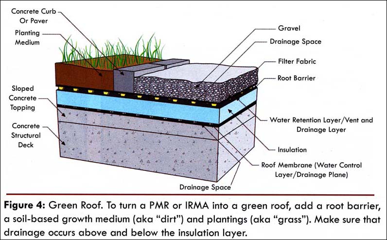
In the following, more generic, image of a green roof, the author makes the point that drainage layers must be present both above and below the insulation layer; the insulation layer "can get saturated if it is not drained above and below."
Disclaimer: Students are responsible for material presented in class, and required material described on course outline. These notes are provided as a tentative outline of material intended to be presented in lectures only; they may not cover all material, and they may contain information not actually presented. Notes may be updated each year, and may or may not apply to non-current versions of course.
first posted Oct. 30, 2012 | last updated: Nov. 18, 2021
Copyright
2007–2021 J. Ochshorn. All rights reserved. Republishing material on this web site, whether in print or on another web site, in whole or in part, is not permitted without advance permission of the author.