Jonathan Ochshorn
This lecture covers brick veneers (two common cavity wall systems) and stone veneer. The two brick systems are as follows:
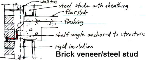
The following diagram illustrates the system, using steel studs as a back-up wall. The purpose of the back-up wall is to provide lateral support for the single wythe of brick that acts as the cladding. It accomplishes this task as follows: metal wall ties are inserted into the mortar joints of the brick courses (at a spacing of approximately 1 tie per 4 square feet of wall surface area, or about two feet apart in each direction), which then span the cavity and fasten to the stud wall. Some early steel stud back-up walls, using light-gauge metal studs, were not stiff enough to prevent cracking of the brick veneer during high winds; heavy=gauge studs are needed to provide adequate stiffness in the back-up wall. If the cavity is insulated, the ties must penetrate the insulation. In any case, they are fastened to the studs themselves, and not to the sheathing, although they penetrate the sheathing to get into the studs. Flashing is shown beginning at the back up wall (possibly as an extension of the air barrier material) and coming over the shelf angle, where it should protrude as a "drip edge" over the joint. Flashing material is traditionally made of corrosion-resistant metals, but can also be fabricated as "fabric flashing" consisting of rubberized membranes. In the latter case, a metal drip edge should still be adhered to the fabric flashing where it extends beyond the surface of the cladding.
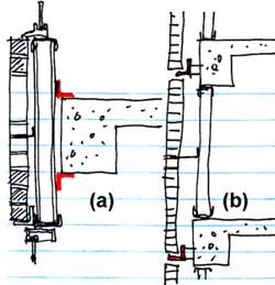
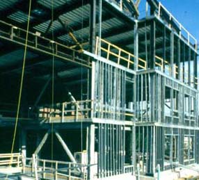
Note that in the case shown above, the back-up wall is supported directly on the structural slab. It is also possible for the steel stud back-up wall to bypass the structure, as is shown in the image below (left). Case (a) shows the back-up wall cantilevered from the structure and bypassing the structure; while case (b) shows the back-up wall spanning from one slab to the underside of the structural girder above. Note that in the latter case, the top support for the back-up wall must permit "sliding" of the wall up and down relative to the position of the structure, i.e., only supporting it laterally. The photo on the right shows the addition to Lincoln Hall at Cornell University during construction of the steel stud back-up wall.
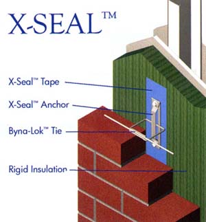
Metal wall ties can be purchased that are coordinated with the insulation within the cavity; that is, they simultaneously hold the insulation in place and provide a lateral tie to the brick. In the proprietary system shown below (X-Seal), the tie can move vertically to accommodate differential movement between cladding and structure, but resists lateral movement of the brick veneer. Note how the tie is embedded within the brick mortar joint.
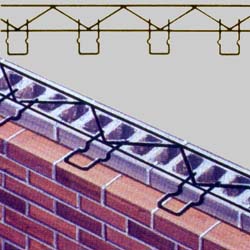
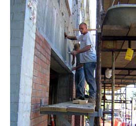
The more traditional use of concrete masonry units (CMU) to back up brick veneer in a cavity wall is similar in section to the use of steel studs. The CMU wall is typically constructed on the edge of the structural slab. Special wall ties provide horizontal reinforcement in the courses of the CMU wall, while also "reaching out" across the cavity to tie the brick veneer to the backup wall. For that reason, the course elevations of the CMU must be coordinated with those of the brick, both systems using an 8" vertical module. An example of such a coordinated system is shown below (left). A more routine example of brick veneer being installed over a concrete and CMU wall (right) is shown on College Avenue, Ithaca, NY (photo by J. Ochshorn). Note the steel shelf angle fastened to the reinforced concrete wall and girder.

See National Lime Association video excerpt.
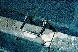
Where windows are inserted into a cavity wall, flashing covers the cavity over the window, so that water cannot enter the building at that point. Additionally, flashing is typically placed under the window sill, for the same reason. In this latter case, the ends of the flashing are turned up, forming a dam, so that water is prevented from moving horizontally across the flashing and entering the building through the window assembly. Note that the idea of flashing across the cavity is problematic, as water may travel horizontally on the flashing, finding seams or other openings, and in that way get into the building. Poorly detailed or installed flashing, or drip edge details, can also lead to such building failures (see image below)
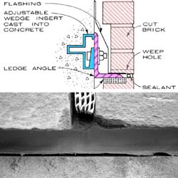
"Ideal" detail from Architectural Graphic Standards (1981) without any drip edge compared with actual, poorly installed, application of drip edge and sealant (Addition to Statler Hall, Cornell University, photo by J. Ochshorn)
See Masonry Detailing Series drawings produced by the International Masonry Institute.
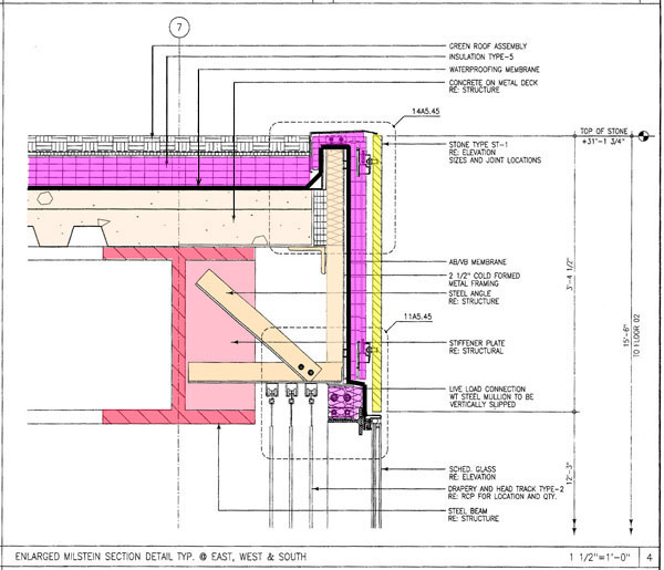
Thin stone can be used as a veneer over a back-up wall. The primary differences between the use of stone and brick as a veneer (cladding) are as follows:
Disclaimer: Students are responsible for material presented in class, and required material described on course outline. These notes are provided as a tentative outline of material intended to be presented in lectures only; they may not cover all material, and they may contain information not actually presented. Notes may be updated each year, and may or may not apply to non-current versions of course.
first posted Oct. 15, 2012 | last updated: Oct. 29, 2015
Copyright
2007-2015 J. Ochshorn. All rights reserved. Republishing material on this web site, whether in print or on another web site, in whole or in part, is not permitted without advance permission of the author.