Jonathan Ochshorn
© 2012 Jonathan Ochshorn. This discussion of web steel (stirrups) in reinforced concrete beams, based on ACI-318 (Building Code Requirements for Structural Concrete) supplements a free online stirrup spacing calculator that I developed. The following symbols or notations are used: Vu = design shear force (includes load factors); Vc = concrete capacity to resist shear in lb units, taken as 2 x b x d x f'c0.5 (where b and d are in inch units and f'c is in psi units); Vs = web steel (stirrup) capacity to resist shear, taken as 2 x As x fy x d / s; b = the "stem" width of the beam; d = the effective depth of the beam; As = the area of a rebar (a single prong only) used as web steel; f'c = the concrete cylinder strength; fy = the yield strength of the web steel; s = the stirrup spacing; and φ = 0.75 (the strength reduction safety factor for shear).
Stirrup spacing calculator
Reinforced concrete beams with uniformly-distributed loads have a shear diagram with maximum positive shear at the left support, maximum negative shear at the right support, and a linear variation between those two extremes. This creates two triangular shear diagrams on either side of the beam's centerline, each with the same absolute values of shear force. For this reason, the required web steel can be determined for a single triangle, and the stirrups deployed there can be reproduced as a mirror image on the other half of the beam. As can be seen in Figure 11, the maximum shear force is actually taken at a distance d from the face of the beam support.
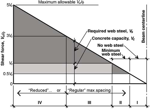
Four zones can be identified within a typical triangular shear force distribution (half-span shown) corresponding to a uniformly-distributed load.
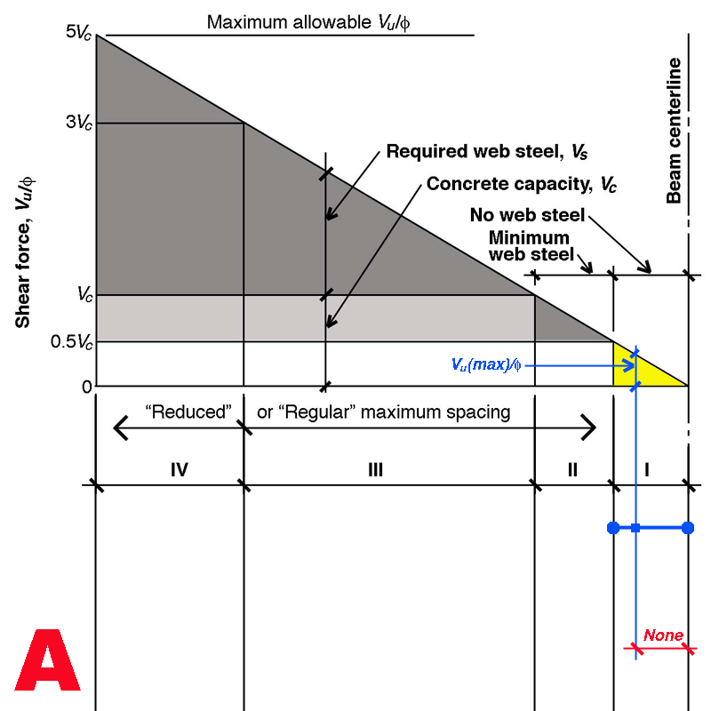
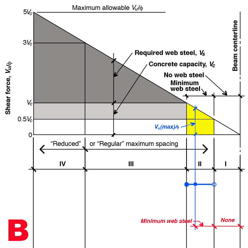
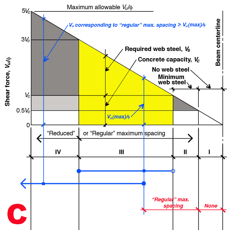
In the shear force diagrams used here, Vu is divided by the strength-reduction factor φ so that its relationship to the steel and concrete capacities to resist shear becomes clearer: Vu / φ = Vc + Vs. Within the shear force triangle, up to four zones may be present: Zone I, where the shear force Vu (divided by the strength reduction safety factor, φ), is less than or equal to 0.5Vc, requires no web steel at all; Zone II is where Vu / φ is less than or equal to Vc (but excluding Zone I) and only requires minimum web steel with spacing, s = 2Asfy/(0.75b × f'c0.5) < 2Asfy/(50b); Zone III is where any calculated spacing cannot exceed the "regular" maximum spacing determined by the smaller of d/2, 24 in., or the spacing corresponding to minimum web steel; and Zone IV is where any calculated spacing cannot exceed the "reduced" maximum spacing determined by the smaller of d/4, 12 in., or the spacing corresponding to minimum web steel. As can be seen in the diagram, the boundary between Zone III and Zone IV — i.e., between "regular" and "reduced" maximum spacing — is defined as the point where Vu / φ equals 3Vc.
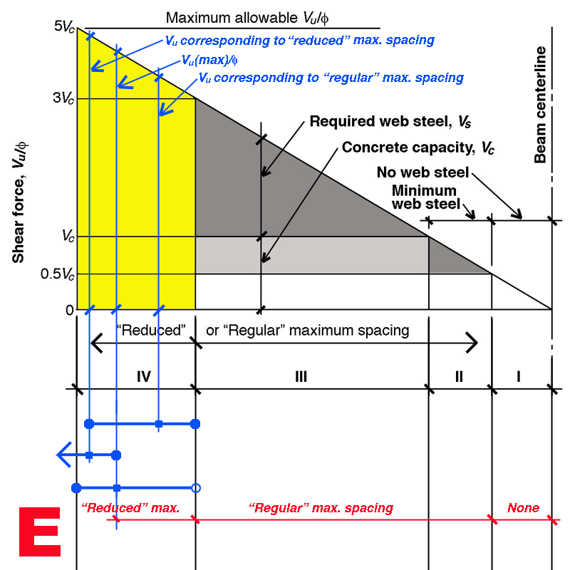
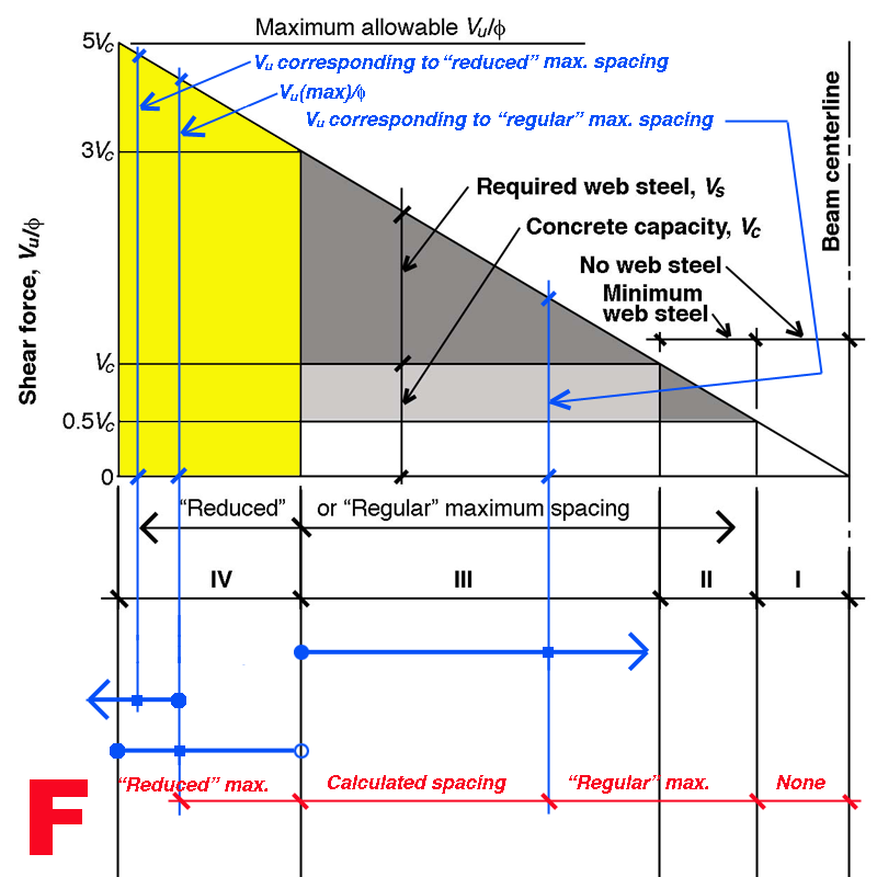
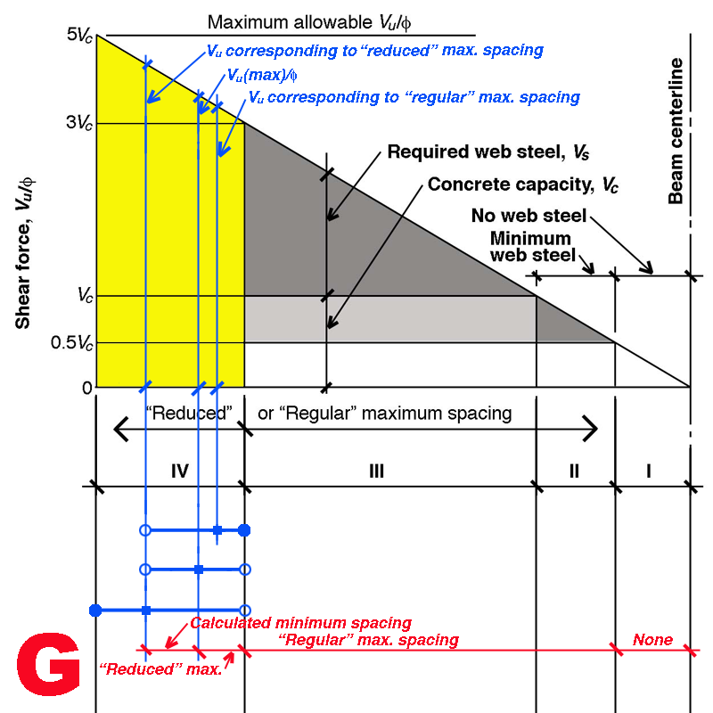
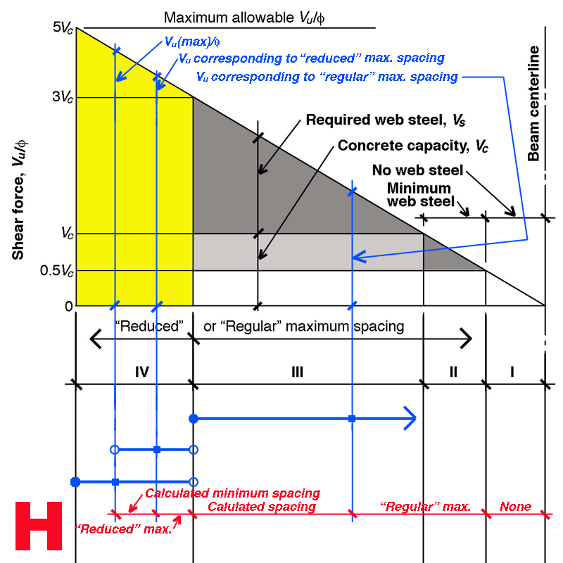
Because the maximum shear force may occur in any of these four zones (shown in Figures 1-9: click on any image to enlarge), and because the computed stirrup spacing at any point along the length of the beam, s = 2Asfyd/Vs, may or may not fall within the limits governed by the two maximum spacing criteria (d/2, 24 in., or min. web steel vs. d/4, 12 in., or min. web steel), there are nine possible patterns of stirrup spacing that can develop, as follows:
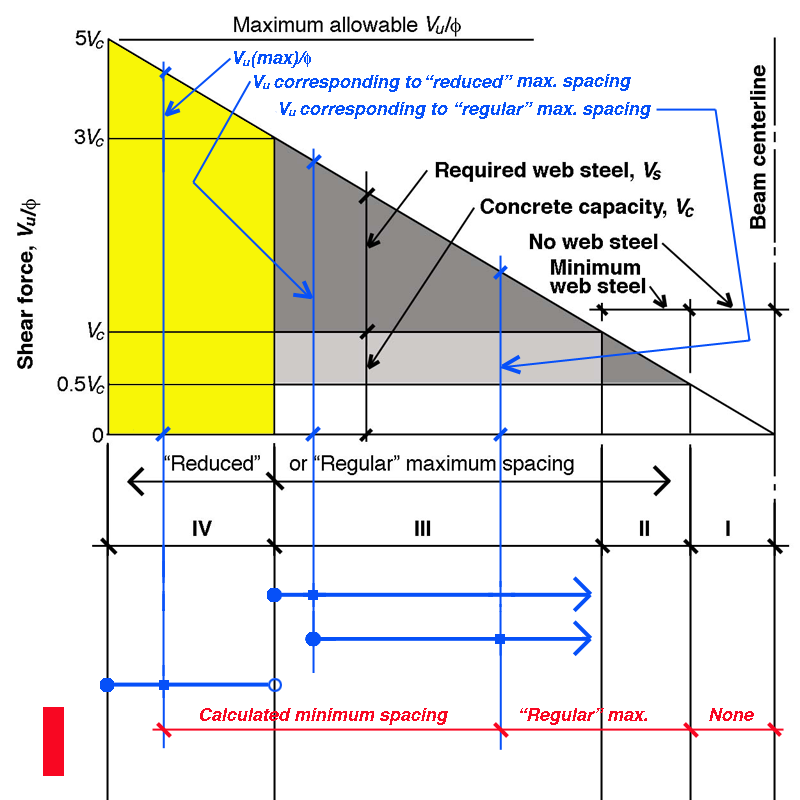
These nine possible patterns, and the stirrup spacing that results, are summarized in Figure 10.

Figure 10. Stirrup spacing begins where the shear force (Vu / φ) is greatest (represented by the thick blue line). Such spacing may be constrained by "regular" maximum spacing limits (the value of Vu / φ corresponding to "regular" maximum spacing is represented by the thick green line) or by "reduced" maximum spacing limits (represented by the thick orange line), depending on where these limits occur in relation to both the maximum shear force (blue line) and the zones in which these maximum spacing limits apply (Zone IV for "reduced" maximum spacing; and Zones III and II for "regular" maximum spacing). "Regular" maximum spacing governs in Zone II, where only minimum web steel is needed, since the criteria for "regular" maximum spacing must also apply. In Zone I, where Vu / φ < 0.5Vc, no web steel (stirrups) are needed. Notice that the value of Vu / φ corresponding to "regular" or "reduced" maximum spacing has no necessary relationship to the zones in which "regular" or "reduced" spacing govern. Thus, for example in Case "I," the value of Vu / φ for "reduced" maximum spacing falls in Zone III where "regular" maximum spacing governs. For this reason, there cannot be any "reduced" maximum spacing within Zone III. And since the calculated required spacing anywhere to the left of this point must be smaller than the value for "reduced" maximum spacing (since the shear force resisted by the web steel increases as one goes to the left), "reduced" maximum spacing is not used in Zone IV either.
The stirrup spacing options described here — based on simplified calculations permitted in ACI-318 (Building Code Requirements for Structural Concrete) — are nevertheless somewhat arbitrary. For example, it is possible to find a single spacing corresponding to the greatest shear force, and to use that spacing throughout the beam. At the other extreme, it is also possible to continuously change the stirrup spacing as the shear force changes along the length of a beam. Between these two extremes, a wide range of choices are possible, including those outlined here. The criterion I have used is to change the spacing at key points where maximum spacing limits become viable. It is, of course, possible to determine additional points governed by intermediate spacings.
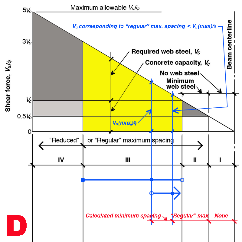
Figures 1-9 show triangular shear diagrams extending from a value of zero at the beam centerline to a maximum value of 5Vc, above which reinforced concrete beams are not permitted. But the "strength-reduced" shear force in an actual beam (i.e., Vu / φ) may never reach that maximum value. As can be seen in Figure 11, these diagrams are not intended to represent the shear forces present in any particular beam, but only the four zones within one of which the maximum shear force, Vu/φ, must occur. Figure 11 shows a uniformly-loaded beam that happens to fall into category "D" shown in Figure 4; that is, the maximum shear force occurs in Zone III, and this maximum shear force is greater than the shear force corresponding to "regular" maximum spacing. In such a case, calculated minimum spacing can be extended from the face of the beam's support (actually, the first stirrup typically starts at a distance s/2 from the face of the beam's support, where s is the initial calculated minimum spacing) up until "regular" maximum spacing controls the design. This "regular" maximum spacing then extends through part of Zone III and all of Zone II up until the point where stirrups are no longer needed (i.e., in Zone I).
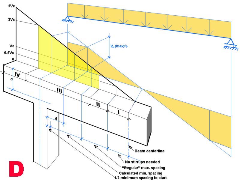
Figure 11. A typical uniformly-loaded beam is shown in the context of the shear force diagram illustrated in Figure 4 (Case "D"). The maximum shear force, Vu, is taken at a distance d from the face of support, where d is the beam's effective depth.
First posted 5 June 2012. Last updated: 27 May 2015