Overview of structure, enclosure, and building systems
Conceptual (schematic) principles of building construction
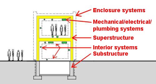
Modern buildings consist mainly of five things:
A foundation (substructure) that transfers the weight of the building to the ground and separates/protects any below-grade spaces from earth and water;
A structural system (superstructure) that rises above grade, supported by the substructure; an enclosure system (AKA skin, building envelope, etc.) including exterior wall cladding, windows, and roofing;
An enclosure system that is supported by and attached to the structure;
Interior finishes attached to or suspended from superstructural elements at floors, walls, and ceilings;
Various electrical, mechanical, and plumbing systems including an ever-expanding list of digitally-controlled systems providing control of comfort, fire-safety, security, communications, and so on.
These can be represented schematically as follows:
Note that Uniformat combines superstructure and enclosure into a single "Division 1" category called "Shell."
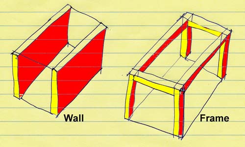
Frames or walls
A foundation system, or substructure, is the precondition for all buildings. These below-grade systems will be discussed in week 11. Once such points of structural support have been established, the superstructure can be built, typically as load-bearing walls, or as a frame.
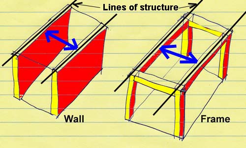
These wall and frame diagrams are incomplete, however. What needs to be established in both cases are the "lines of structure" that provide consistent support for horizontal floors or roofs. In the simplest, and most common, model, these lines of structure are parallel to each other, and equally spaced, so that a floor/roof slab or deck can be constructed that spans between these lines. To the extent that the lines of structure are inconsistently spaced or inconsistently oriented, the horizontal spanning elements for the floors and roofs need to respond differently for each different condition encountered.
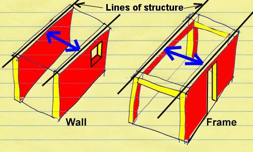
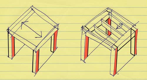
Before examining the horizontal surfaces used for floors or roofs, it should be pointed out that lines of structure can be established by any combination of posts (columns, piers, etc.) or wall elements:
Hierarchy or horizontal spanning elements: Horizontal floor or roof surfaces can be established in many ways, once lines of structure have been determined.
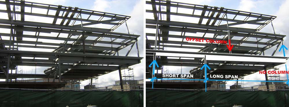
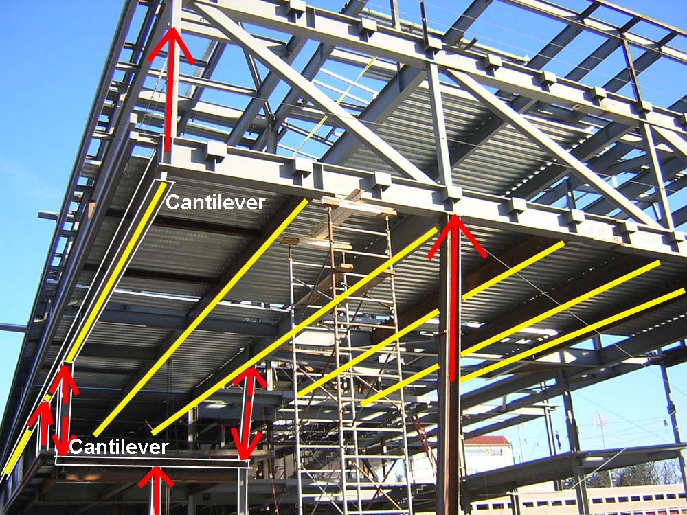
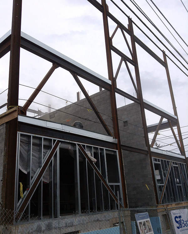
Morphosis, Gates Hall at Cornell, under construction, showing how lines of structure are established using girders of various depths corresponding to their spans and loads. The girder missing a column at the far right is actually supported by a cantilevered truss perpendicular to the girder that is visible in the image (photo by J. Ochshorn). Morphosis, Gates Hall at Cornell, under construction: lines of structure (shown highlighted in yellow) are fairly regular, supporting a corrugated steel deck for the floor structure; the structural support for these lines of structure is highly complex, with some of the load paths shown with red arrows (photo by J. Ochshorn).
Aside from two-way reinforced concrete slabs, which are capable of spanning in two directions simultaneously, all other structural floor/roof systems (including many constructed with reinforced concrete) contain a hierarchy of elements beginning with the lines of structure (for bearing walls) or creating the lines of structure (with frame systems).
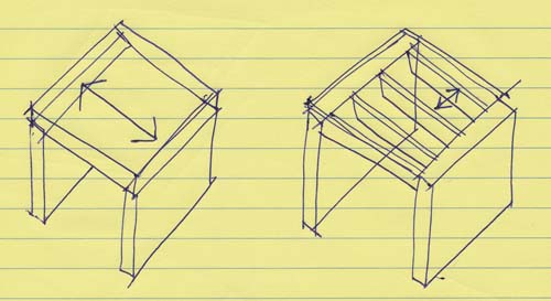
Bearing walls and 1-way slabs/decks: The diagram below (left) shows a 1-way slab resting on, bearing upon, or spanning between two walls. Another level of hierarchy can be established by having closely spaced beams (joists) span between the bearing walls (right). In this case, a slab or deck must span between the joists to establish the floor or roof surface. Each level of structure, starting with the elements establishing the primary lines of structure, span perpendicular to the elements to which they are fastened or upon which they bear. This pattern or hierarchical relationship can go on indefinitely, with smaller and smaller elements fastened perpendicular to the prior level. In practice, the most common hierarchical patterns with load-bearing walls are slabs/decks on walls; and slabs/decks on joists on walls.
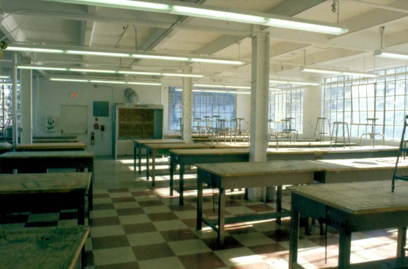
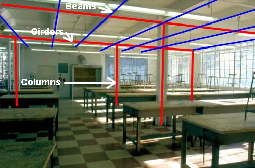
Columns, girders, beams; and slabs/decks: Where the lines of structure are established with frames, a new set of structural elements come into play: columns and girders. Girders are beams that span between columns; i.e., they are hierarchically the primary horizontal spanning elements in frame structures, and they establish the lines of structure, effectively replacing bearing walls.
Many variations of column-slab systems are possible, especially in reinforced concrete structures (left). Perhaps the most common structural system, excluding simple light wood-frame structures, consists of columns, girders, beams, and slabs/decks (right). The spanning distances between all these elements depends on the loads being supported, the material strengths and stiffnesses of the elements, and the size of those elements. In general, longer spans require deeper structural spanning elements.
Extension of wall or frame idea horizontally: Any of the structural variants discussed above can be extended horizontally to provide structural support for any size plan. The actual spacing between columns (column "grid" dimensions) depends on loads, strength and stiffness of materials, foundation conditions, interior planning considerations; floor-to-floor height constraints (since deeper structural spanning elements take up more room vertically, but provide greater spans/ fewer columns), and so on.
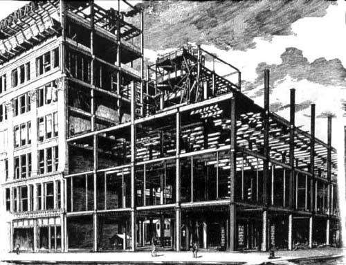
Extension of wall or frame idea vertically: Just as any of the structural schemes discussed above can be extended horizontally, they can also be extended vertically. The famous image of Jenney and Mundie's Fair Store in Chicago (built in 1892) reproduced below shows how frame structures are extended both horizontally and vertically.
Nothing much has changed, except that the spanning capacity, based on the increased strength of structural materials, is much greater today. Details of connections and floor systems have also changed, but the basic concept of the frame has survived.
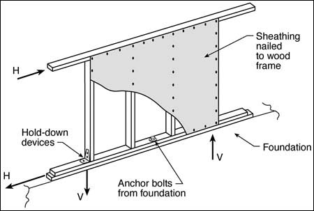
Bracing of wall or frame systems against horizontal loads: The diagrams of wall and frame systems shown above only resist downward-acting (gravity) loads. It turns out that this is the easy part. The hard part (in furniture as well as in buildings) is resisting horizontal (lateral) loads, typically caused by wind or earthquakes (seismic forces), but also by impact loads of all kinds.
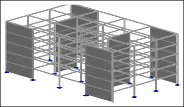
For bearing wall buildings, the typical strategy is to build more walls, perpendicular to the "load-bearing" ones. The two sets of walls brace each other, much like building a house of cards. House of cards (image source); and of course, there are these completely unrelated House of Cards references: a video by Radiohead and a TV drama.
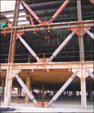
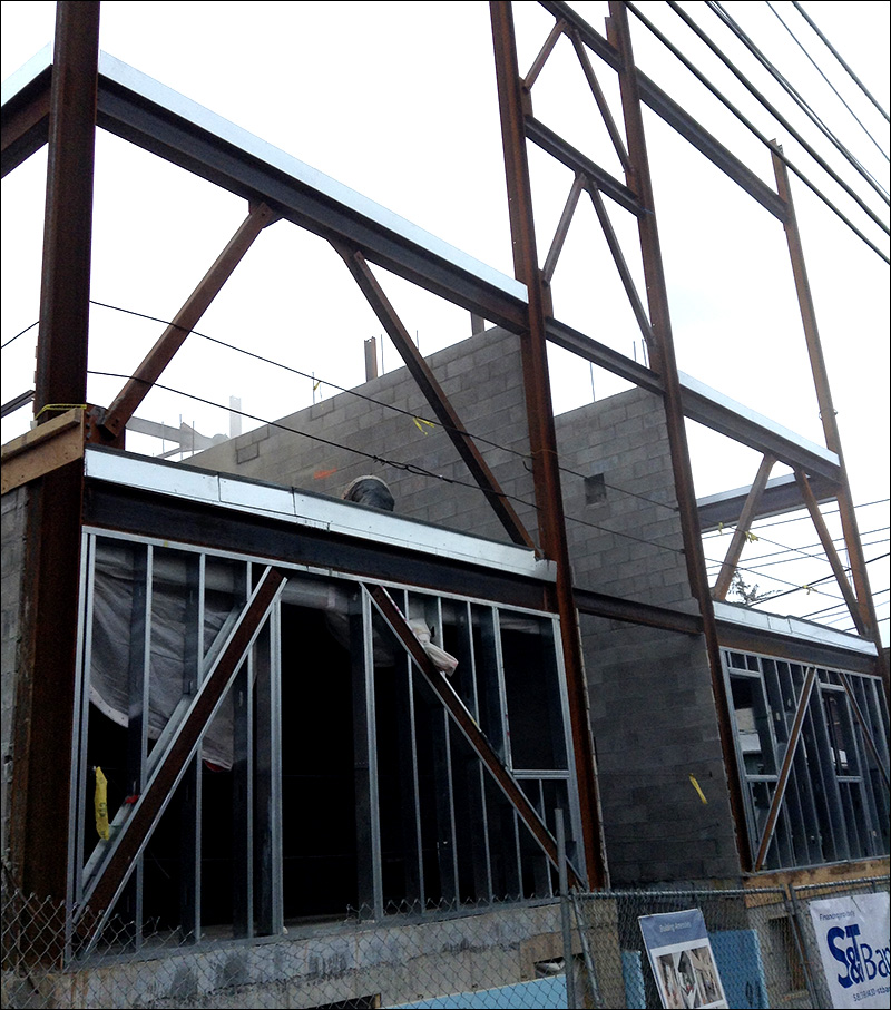
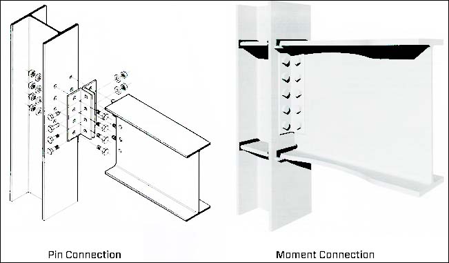
For frame buildings, there are really three bracing strategies:
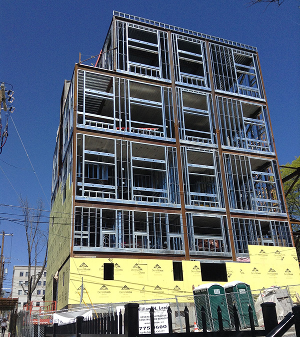
Ad hoc and pragmatic diagonal bracing of steel frame (notice how the bracing is offset to accommodate window openings and also how the apparent capacity of the bracing is reduced on the upper floors where bending moments caused by lateral forces are smaller—College Avenue, Ithaca, NY; photo by J. Ochshorn, 2017 — see case study below)
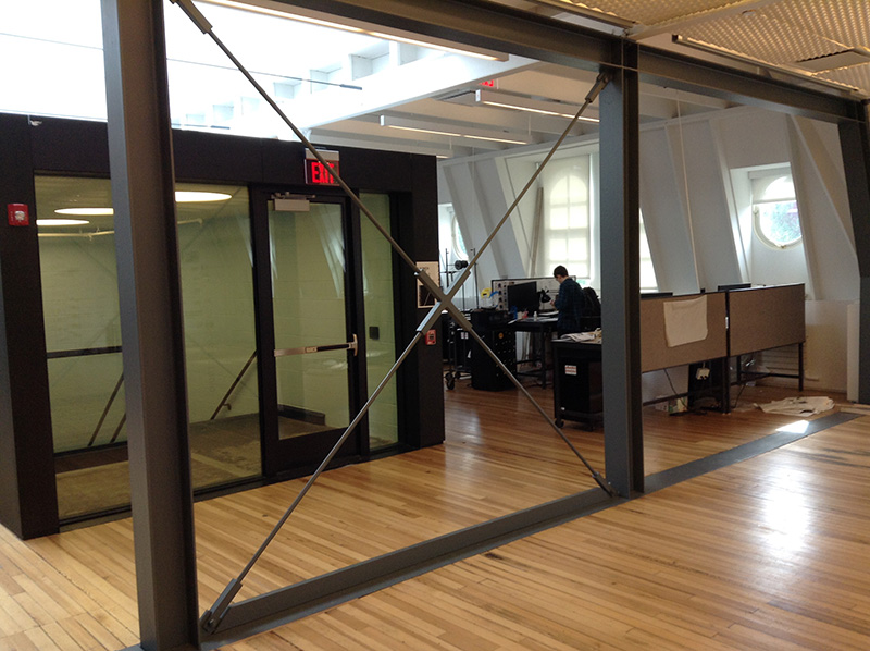
Diagonal X-bracing in Sibley Hall, Cornell (3rd-floor replacement of brick shear wall; photo by J. Ochshorn, Oct. 2015)
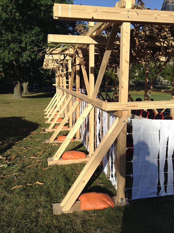
Diagonal wooden bracing on temporary "sukkah" built on Arts Quad at Cornell by architecture students, October 2017 (photo by J. Ochshorn, Oct. 2017)
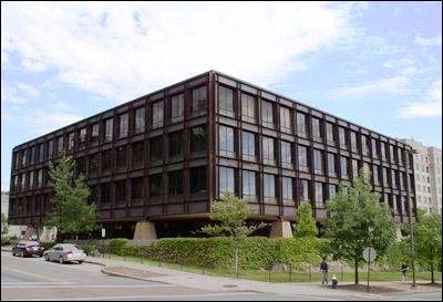
Example of rigid connections: Uris Hall, Cornell, S.O.M.
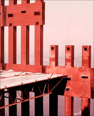
Example of rigid connections: World Trade Center, NYC
Enclosure systems
Two strategies exist for enclosing a superstructure -- i.e., separating the interior from the exterior spaces.
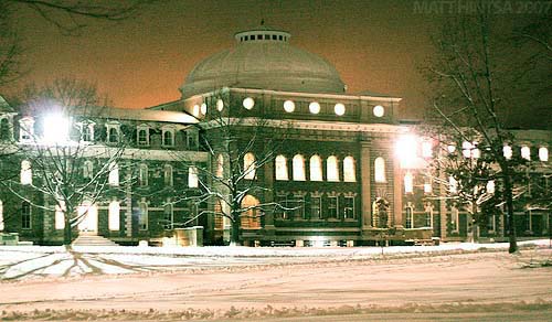
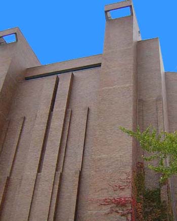
In certain cases, the exterior load-bearing walls can simultaneously act as enclosure elements. Openings are typically punched in the exterior walls in order to bring in controlled amounts of light and air, and those windows also constitute part of the enclosure system. Sibley Hall at Cornell may serve as an example of that strategy. But modern masonry load-bearing wall systems that simultaneously act as enclosure systems are still used.
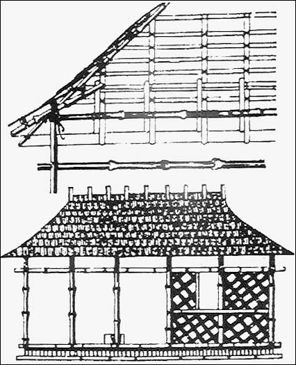
More typically in modern construction, either the bearing walls or the structural frame support a separate and distinct enclosure system (skin, cladding. envelope, etc.). The distinction, and necessary relationships, between frame and cladding were theorized by Gottfried Semper (1803-1897), who proposed a 4-part division of architecture into earthwork, hearth, frame, and cladding, where the stereotomic -- seen in earthwork and heavy masonry -- and the tectonic -- seen in the framed roof structure -- were contrasted with woven or fabric enclosure elements supported from the framework. The so-called "primitive hut," shown below, was the archetypal example of such a scheme.
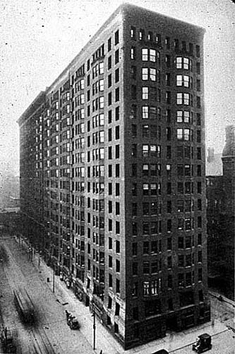
Thick exterior masonry bearing walls, acting as enclosure systems, were capable of absorbing water (which could then evaporate before penetrating interior spaces) and mediating extremes of temperature (thermal mass). However, there were both practical and cultural/stylistic limits with such walls -- limited heights, limited area for glazing, limited opportunity for structural or formal gymnastics, limited ability to provide thermal insulation -- and structural frames became more important in the late 19th century. Monadnock Building, Chicago, Burnham & Root, 1891
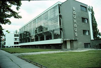
Early cladding systems (as in Rand Hall, Cornell) were quite similar to the load-bearing walls they seemed destined to replace. In fact, some of such early masonry "cladding" was so tightly integrated with the structural frame that the structural behavior of frame and cladding could not be separated. Soon, in the early-mid 20th century, such cladding systems became more distinct and separate: the "curtain wall" was born. Walter Gropius, Bauhaus, Dessau, Germany, 1925-1926
Curtain wall systems consist of various materials (glass, metals, masonry, concrete) that are fastened to the building's superstructure, typically a structural frame, to provide enclosure on the vertical surfaces of the building. Such enclosure has several purposes:
Provide a barrier to water (rain, snow)
Provide a barrier to unwanted heat loss and heat gain
Provide a barrier to water vapor so that it doesn't condense within the wall itself
Provide a barrier to the movement of air
Provide a barrier to living things of all kinds (insects, birds, bacteria, etc.)
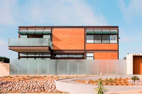
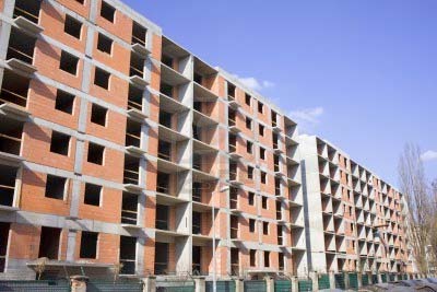
The attachment of the curtain wall to the structure generally happens at each floor level. In Brutalist buildings, as well as in their modern progeny, the concrete slab or steel frame, often exposed, becomes the surface on which the cladding elements rest. House, Macy Architecture, Sustainable Steel House, San Diego, CA Apartment house, concrete frame and brick infill, under construction
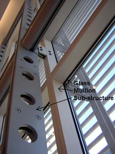
In more classic curtain wall construction, the frame is covered by the cladding system that it is supported by, typically at each floor level. Horizontal floors provide a more predictable, consistent, and smaller dimension for such curtain wall spans than would the vertical columns of the structural frame. In the image below, an additional "substructure" is constructed between the floors in order to decrease the span of curtain wall mullions in a double-height cafeteria space. Detail, curtain wall support in cafeteria, NY Times Headquarters, Renzo Piano (photo by J. Ochshorn)
Electrical, mechanical, and plumbing systems
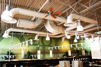
Conduits and pipes are generally pretty small; they can often be installed between the enclosure and interior finishes on the exterior wall, or between the structural floor/roof and suspended ceiling systems that characterize many buildings. Where raised access floors are used, they can be placed between the finished floor and the structural floor. In such cases, where enough "hidden" space is provided for such things, the design of electrical, plumbing, and mechanical systems can proceed more or less independently from the design of the building form and its interior spaces. Alternatively, such systems can remain exposed or tightly coordinated with enclosed spaces provided in the building. At the extreme, they can form an integral part of the building's expression. Bradfield Hall, Cornell, Ulrich Franzen, 1969 (photo by J. Ochshorn)
Exposed mechancial ducts at Whole Foods Store (photo credit)
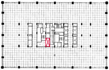
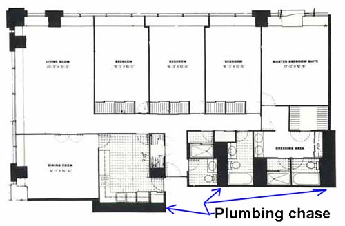
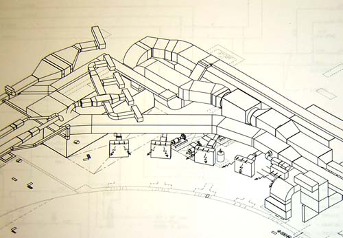
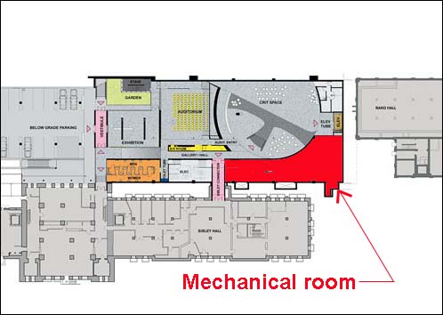
Where ductwork, cables, or conduit is too large to simply hide within a wall or floor, it is common to create a "chase" or shaft linking various floors.
1. Steel framing with cross-bracing in place; steel studs provide a substructure for sheathing (not yet installed), leaving rough openings for windows; floors are precast concrete planks.
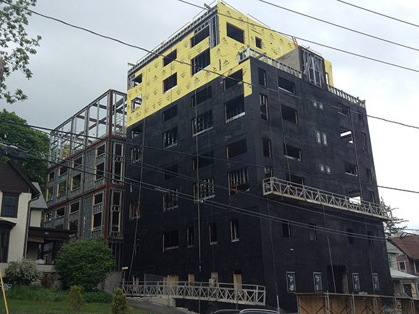
2. Exterior sheathing is screwed into steel studs.
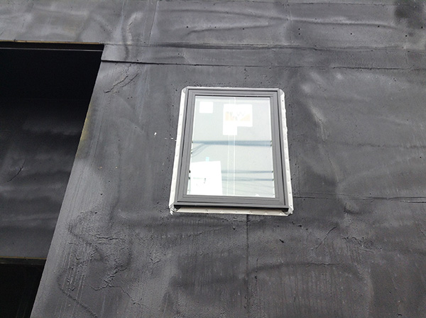
3. Spray-applied air barrier on sheathing (may also act as water/vapor barrier).
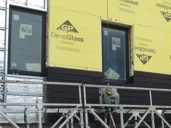
4. Windows with integral flange-flashing screwed into studs which frame the rough opening for the window.
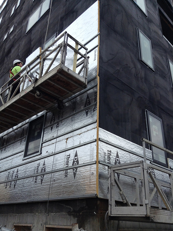
5. Dow "Thermax" insulation screwed into studs, over air barrier, with metal "furring" strips. These metal strips are appropriately spaced for attachment of the insulation, but not for the cladding.
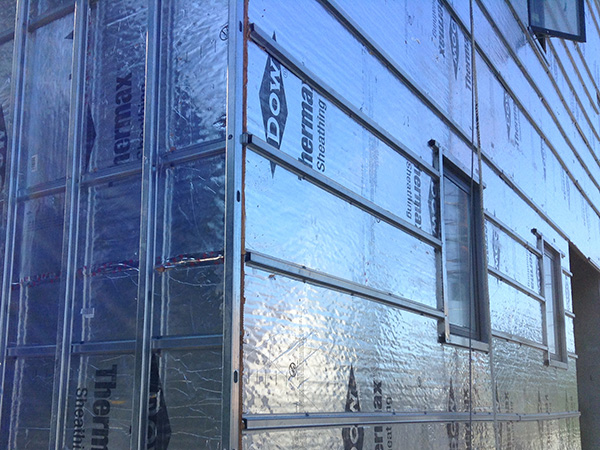
6. Vertical studs are screwed into horizontal furring, spaced appropriately for the cladding.
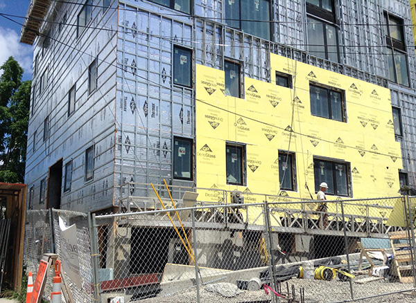
7. A second layer of exterior sheathing is attached to vertical studs, but only where bamboo composite siding will be used (possibly to meet requirements for a fire-resistant barrier on the exterior of the insulation?).
8. Bamboo composite siding is clipped into place (with clips screwed into vertical studs) over exterior sheathing.
9. Thin (1/4-inch) fiber-cement panels are screwed into vertical studs, placed between vertical and horizontal metal flashing "reveals." These do not require exterior sheathing, presumably because they already provide adequate fire resistance for the insulation.
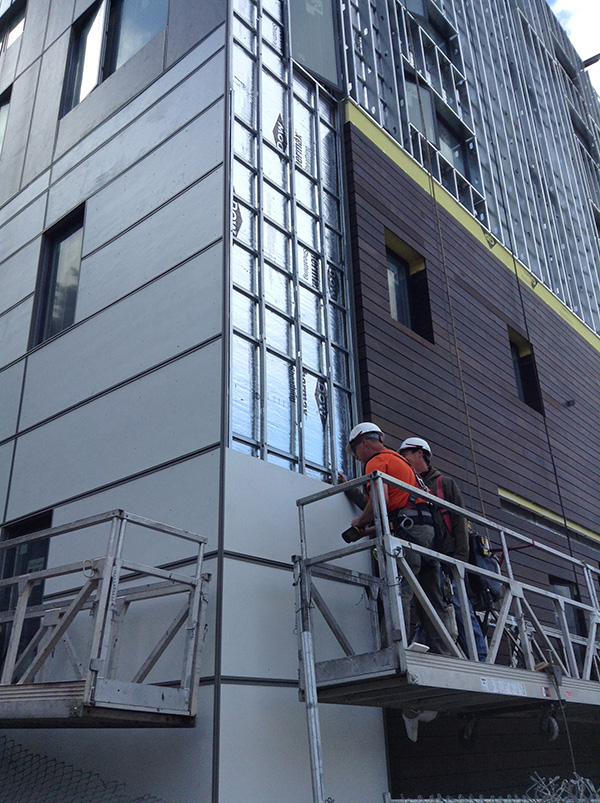
10. 201 College Ave., Ithaca. NY: Installation of cladding panels. Panels are screwed into studs after being inserted as shown.
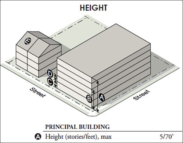
11. Here is an excerpt from Ithaca's special zoning requirements ("Collegetown Area Form Districts") for this site: height limits are 5 stories and 70 feet. The apartment building appears to have 8 floors plus a basement (entry level). How is this possible?
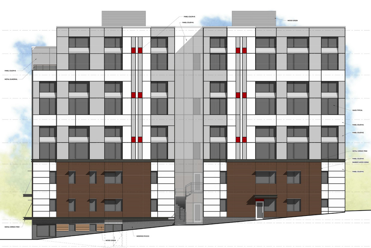
12. It appears that the top three stories contain "mezzanines" which count as "floors" but not as "stories" in modern building codes. Mezzanines cannot exceed 1/2 the area of the room or space they are in (1/3 the area if the building is not sprinklered), so the floors are set back, creating double-height living spaces. This would explain how the building becomes 5 stories; the height limit (70 feet) is harder to meet, but not impossible if the minimum floor-to-floor height of 10 feet (per Zoning requirements in this district) is interpreted as a minimum "story-to-story" height. In that case, the bottom two stories could be 10 feet each, with the three double-floor mezzanine apartments being 16.67 feet each (allowing just enough space above and below the mezzanine). Elevation by Stream Collaborative.
Disclaimer: Students are responsible for material presented in class, and required material described on course outline. These notes are provided as a tentative outline of material intended to be presented in lectures only; they may not cover all material, and they may contain information not actually presented. Notes may be updated each year, and may or may not apply to non-current versions of course.
first posted Oct. 9, 2012 | last updated: October 18, 2021
2007-2021 J. Ochshorn. All rights reserved. Republishing material on this web site, whether in print or on another web site, in whole or in part, is not permitted without advance permission of the author.