Fall 2020
Jonathan Ochshorn
Issued Nov. 2, 2020
Due Nov. 9, 2020, 3:00 pm (upload PDF to canvas)
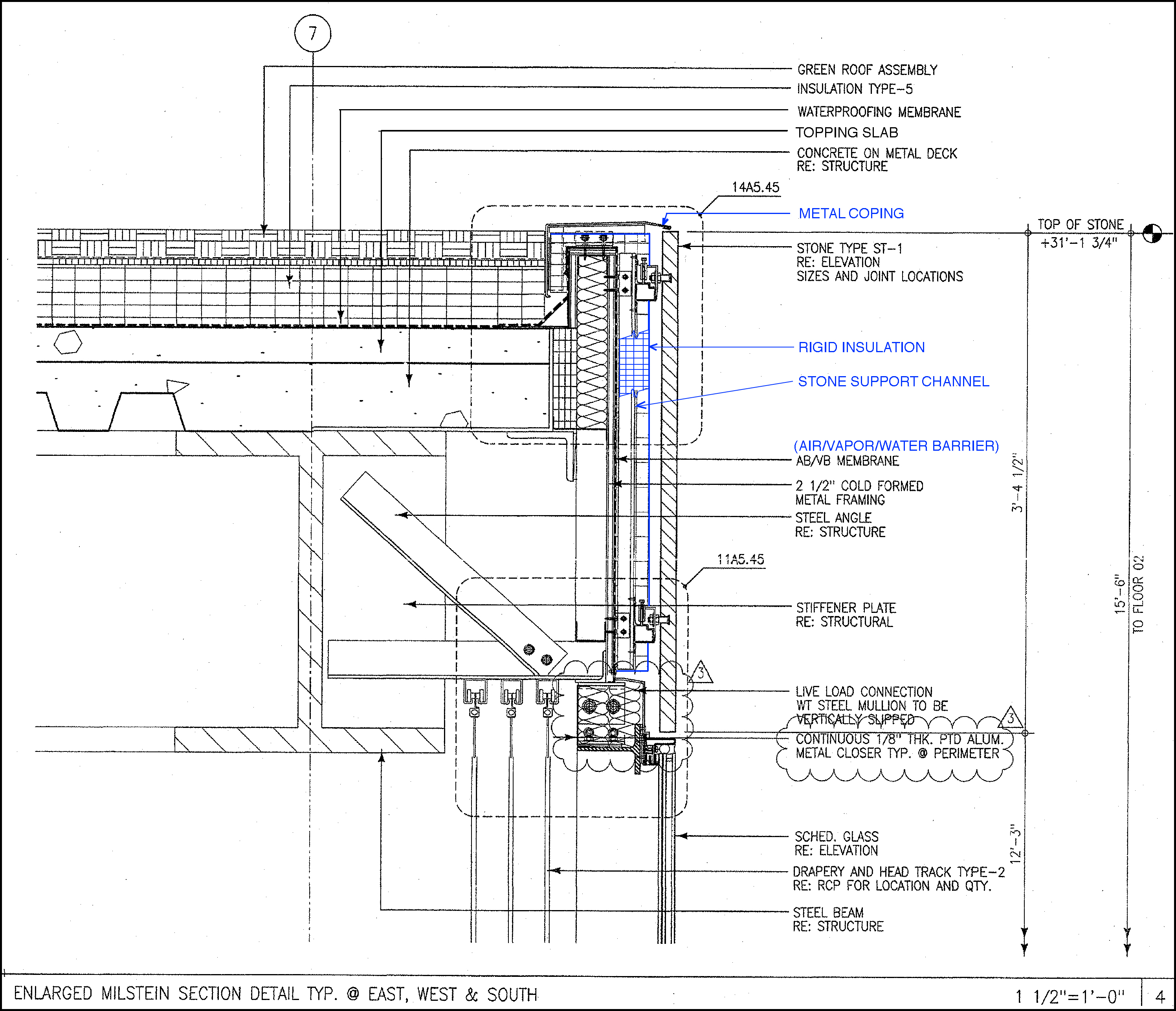
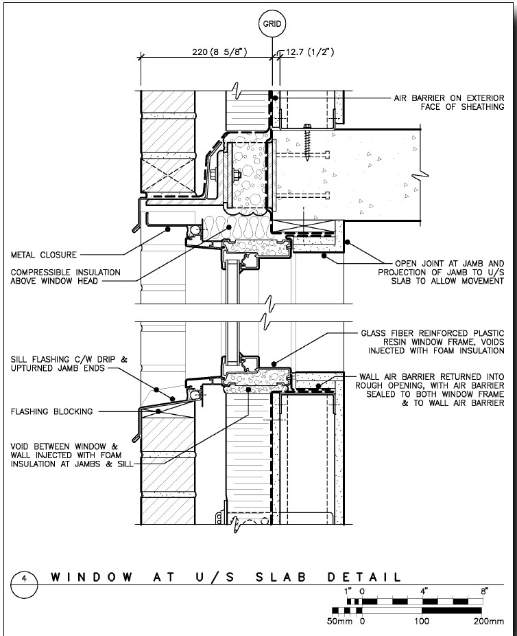
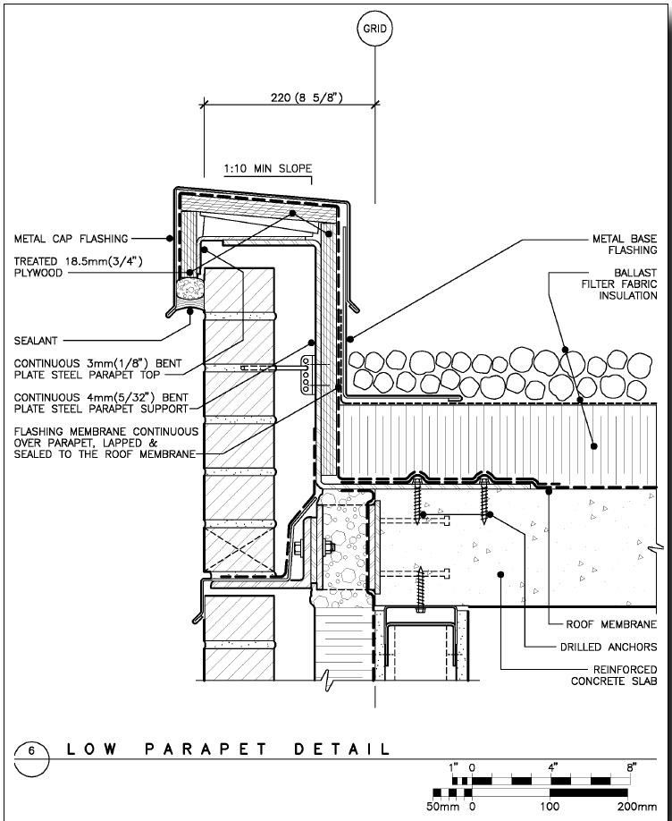
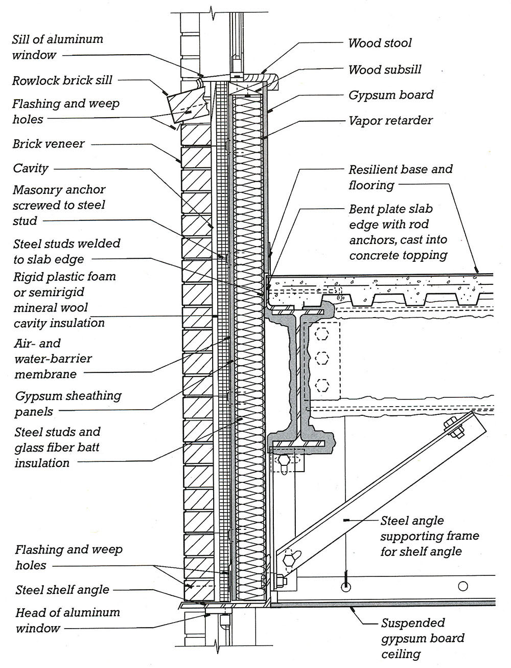
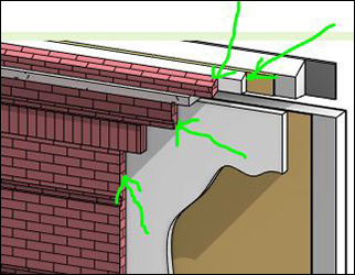
Detailing often involves modifying conventional standards in order to express a particular design idea. Often, several "standard" details are combined and/or adapted to achieve this goal. In this assignment, you are asked to modify the existing detail at the intersection of the stone veneer and green roof of Milstein Hall, shown in the detail reproduced below. Examine the existing detail, as well as the other references provided, in order to create a new detail according to the requirements listed below.
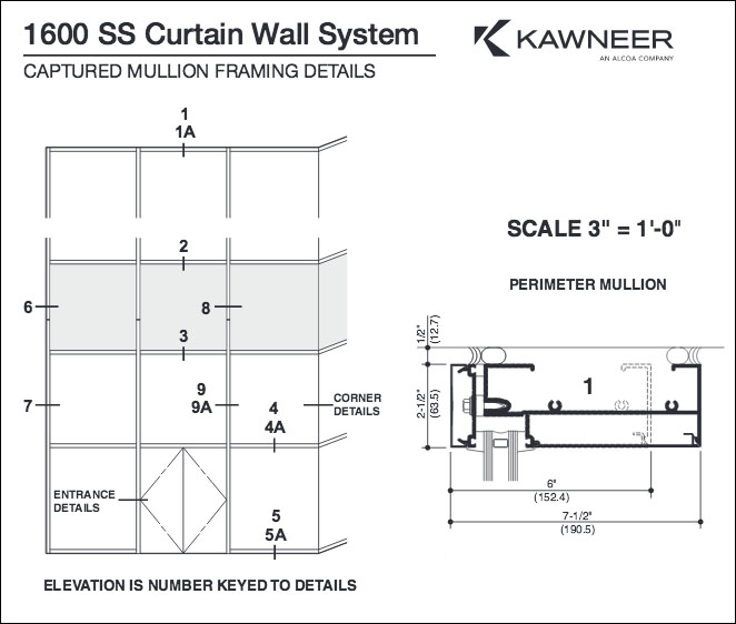
Draw a detail section at the wall-roof intersection of Milstein Hall, at a scale of 3" = 1'-0" (or 1:4 in metric scale; twice the size of the Milstein Hall detail shown in the lecture notes and reproduced below). However, alter the detail in the following ways: a) use BV/SS in place of stone veneer at the fascia just below the green roof, and b) use a conventional aluminum and glass curtain wall system with vertical mullions and horizontal rails at the sill and head (it is only necessary to include the "head" detail).
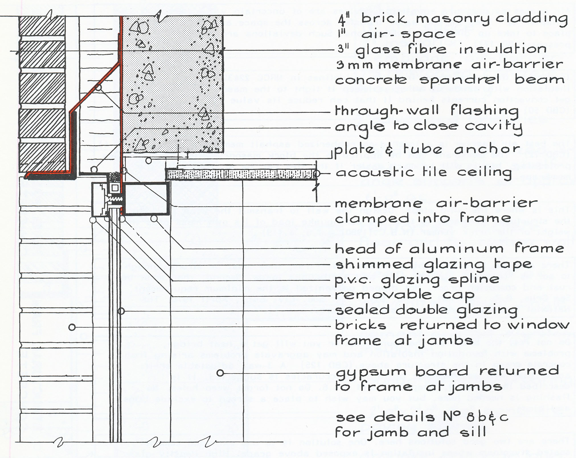
Other sources of information:
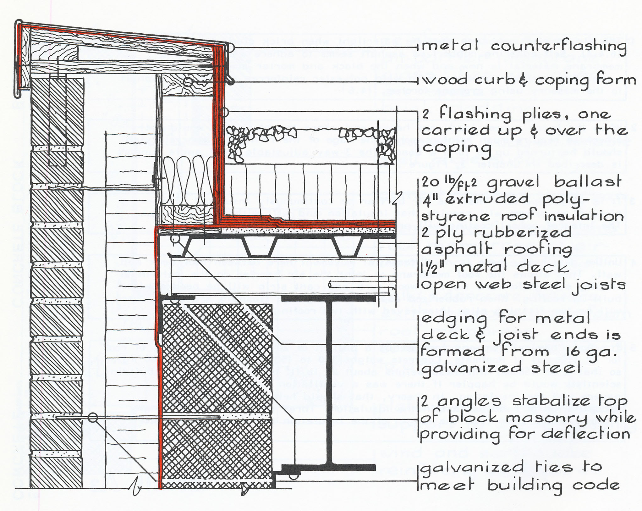

You'll notice that nothing seems to work perfectly; you want a steel stud backup wall, but some of the details show CMU; or you may want a green roof, but some details show more conventional roofs. Or the exterior is shown on the right, but in the details, the exterior is on the left. And so on. Feel free to do more internet-based searches to find other sources of information. Ask questions!
Some notes on the section:
Scale: 3" = 1'-0" (or 1:4 in equivalent metric scale)
Refer to Chapters 20 and 21 of the text (Details 20.5 and 21.11 may be useful), the International Masonry Institute Detailing Series, Architectural Graphic Standards and other references linked from the course readings page, and the Milstein detail and video linked from the lecture notes.
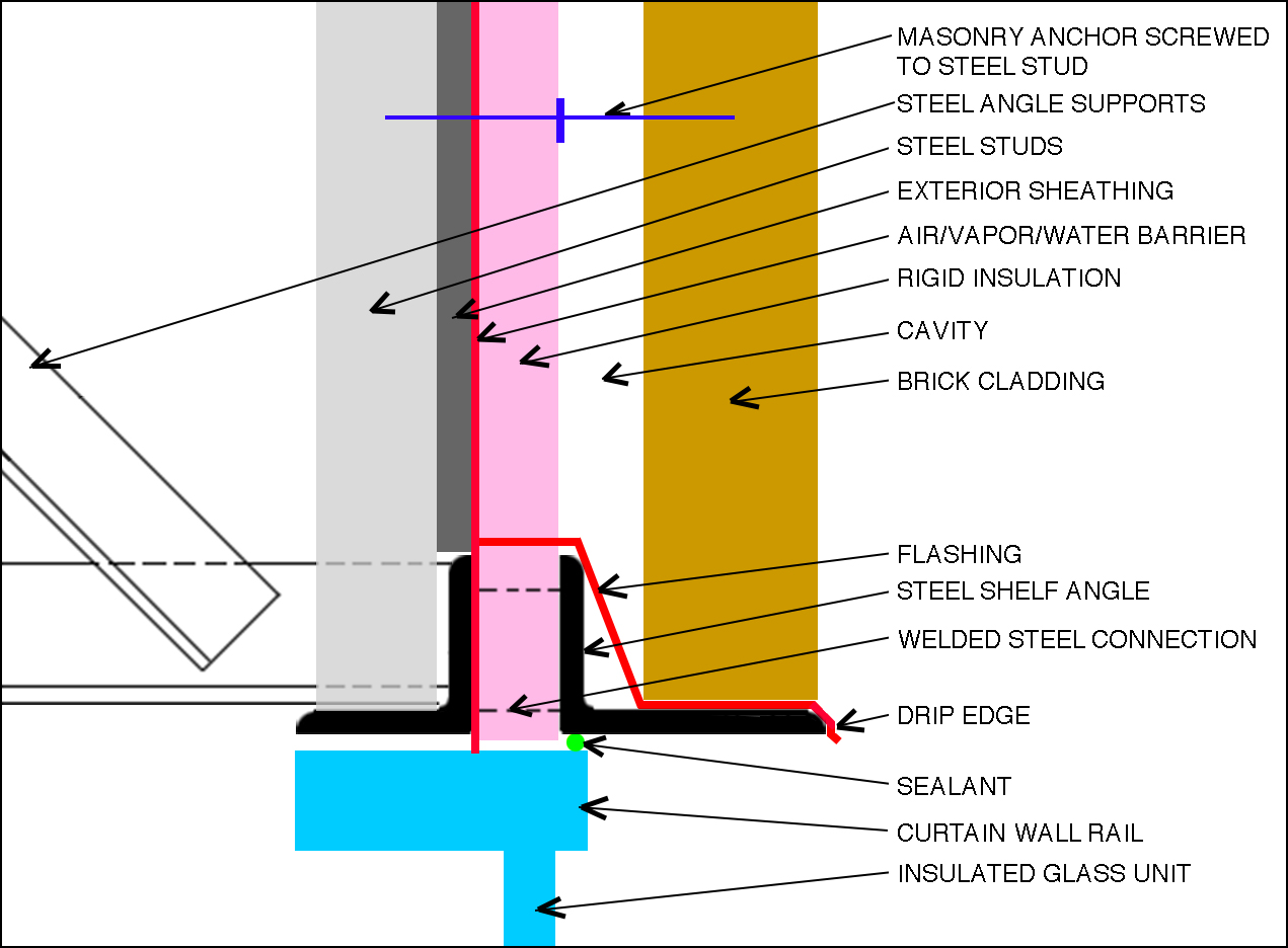
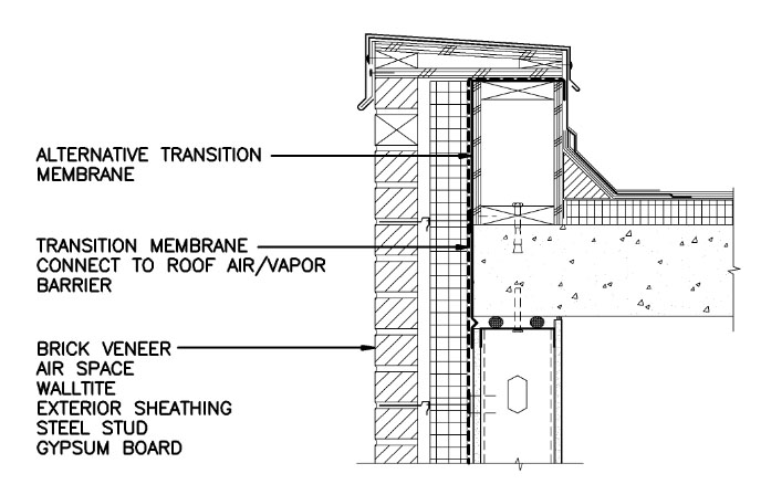
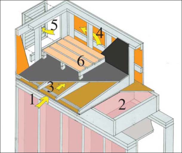
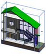
Include insulation and try to minimize thermal bridging by aligning the rigid insulation with the insulated glass units in the curtain wall as shown in the schematic section.
Review Section 4.2 Drawing Standards and Section 6 Symbols in the National CAD Standard (Uniform Drawing System, Module 4 — Drafting Conventions and Section 6.0 — Symbols).
The overall form and features of the building should remain pretty much as they are shown in the as-built drawing above (position of structure relative to facade, etc.), but you will need to modify existing details, in addition to the required modification of the cladding and glazing system. Label all elements in the drawing ("notations"), and provide dimensions and datum heights as in the original detail.
Do not simply copy "lines" from the original detail (or any other detail) unless you understand what those lines represent.
Pay particular attention to the continuity of all four control layers (thermal, vapor, rain water, and air), especially at the intersections of wall and glazing; and wall and roof. The air-vapor-rain water control layer can be combined as a single "rubberized" membrane applied directly over the exterior sheathing in the cavity (and rendered as a thick line); the thermal control layer can be 2"-thick rigid insulation adhered to the air-vapor-rain water membrane. The cavity (i.e., the air space between the insulation and the brick cladding) should be about 2 inches wide, and bricks can be drawn as approximately 4 inches wide. The height of typical bricks is about 2-2/3 inches nominally, i.e., including the mortar joint (so that the centerline-to-centerline height of 3 bricks courses is exactly 8 inches). The steel studs supporting the exterior sheathing can be assumed to be 3⅝ in. wide, with ⅝ in. sheathing.
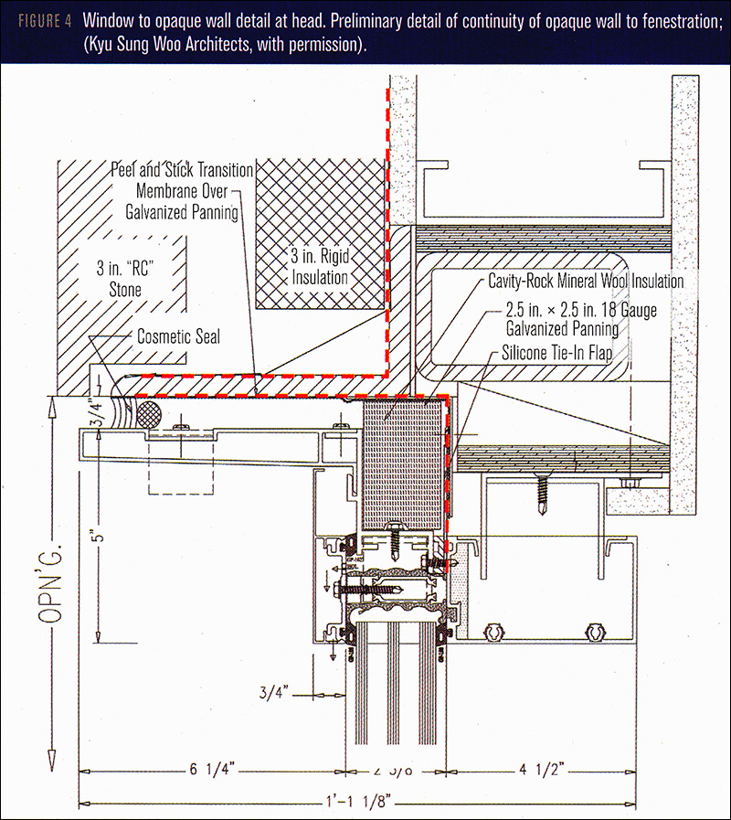
You may assume that the horizontal curtain wall "rails" are fastened to the vertical mullions which are, in turn, fastened to the structure. Therefore, there is no fastener connecting the horizontal rail to the building structure in the section you are drawing. Also note that the Kawneer detail is for a curtain wall head, whereas the CMHC detail is for a window head, which may not be appropriate in this case.
As seen in the Milstein Hall curtain wall video, the steel support system for the glazing is quite complex, and not appropriate for a standard cavity wall and curtain wall. Therefore, please design something simpler to support a shelf angle for a brick fascia. In fact, this is the main challenge of the assignment — to figure out how to support a shelf angle for a brick fascia above a standard curtain wall. Feel free to follow the strategy shown in the schematic section above, but draw the elements as they would be represented in a working drawing at this scale (e.g., curtain wall rail, steel studs and sheathing, insulated glass unit, individual bricks and mortar joints, etc.). Use accepted rendering conventions for materials that are cut in the section. Elements shown "in elevation" are not typically rendered. Typical symbols for materials shown in section can be found online (for example, here) or in the NCS (see Uniform Drawing System, 6.0 Symbols).
Follow the guidelines in the NCS for this type of detail section; use black only (no colors).
Make a 3-dimensional cut-away drawing of the sectional detail. The idea is to show the same elements (e.g., steel girder, shelf angle, insulation, air-vapor barrier, brick veneer, brick ties, green roof layers, curtain wall horizontal "rail," vertical mullion, and glazing, etc.), but in a manner that illustrates exactly what they look like. In other words, you should be able to show the drawing to any non-architect to explain how all the systems work. In particular, try to show the continuity of the various control layers.
Do not label the various elements. However, color (even if exaggerated) can be useful in distinguishing one element from another, and in demonstrating the continuity of control layers.
Some notes on the cut-away drawing:
Make a three-dimensional view (isometric, axonometric, elevation oblique, or perspective) of the "revised" Milstein Hall window head, brick veneer fascia, and green roof detail illustrated in the modified Milstein Hall section you have drawn.
Use a cut-away technique to reveal all the constructional elements and connections that might be obscured otherwise. In other words, don't just show a sectional view that has been "extruded" into a three-dimensional drawing, but rather cut-away at the various layers so that they are each revealed as three-dimensional objects and not just glorified lines or textures as in a two-dimensional view.
The trick and challenge of using a cutaway technique is to simultaneously show how the building really looks while also showing how the building really works.
Scale: The 3-dimensional drawing can be at any scale. The concept of "scale" applies to isometric, axonometric, and elevation oblique drawings, but is less clear in the case of perspectives, which, in any case, still need to be correctly constructed so as to accurately reflect the proportions of the objects being represented.
No labeling or dimensions are required, but draw to some consistent scale.
Show continuity of roof-wall insulation and air/water/vapor barriers.
You may assume that the steel angle triangular supports and the welded steel connections between the two angles are 4'-0" on center; that brick ties are approximately 2'-0" apart both vertically and horizontally; and that the steel studs supporting exterior sheathing are 16 inches on center.
Use of color is encouraged to clarify the different materials, layers, and connections.
Format the assignment on any size sheet listed in the NCS, with a border and title block following the NCS guidelines.
Copyright
2012–2020 J. Ochshorn. All rights reserved. First posted: Nov. 12, 2019 | last updated: Nov. 2, 2020