Contents |
Introduction to structural design | Statics | Tributary areas | Equilibrium | Reactions | Internal forces | Indeterminate structure | Material properties | Strength of materials | Sectional properties | Construction systems | Connections |
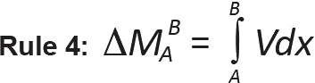
Table A-1.1: Derivation of rules for drawing shear and moment diagrams1
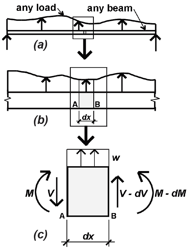 |
Take any beam with variable load, as shown at left (diagram a). Then take an elemental slice of the beam with length, dx, and average load, w, over that length (diagram b). There is a shear force and moment on the left face of the element (V and M), and, because the load, w, is assumed to act in an upward direction (positive), there is a slightly smaller shear and moment on the right face (diagram c). Rules 1 and 2 derive from the vertical equilibrium of that elemental slice, while Rules 3 and 4 derive from the rotational equilibrium of the same element. |
From vertical equilibrium: |
Rule 1: w = dV/dx
|
From rotational (moment) equilibrium: |
Rule 3: V = dM/dx
|
Note:
1. The four rules are expressed mathematically in the Table A-1.1; they may also be expressed in words, as follows:
Rule 1: At any point along a beam, the slope of the shear diagram equals the value of the load (the "infinite" slope of the shear diagram at concentrated loads can be seen as a shorthand approximation to the actual condition of the load being distributed over some finite length, rather than existing at a point).
Rule 2: Between any two points along a beam, the change in the value of shear equals the total load (between those points).
Rule 3: The slope of the moment diagram at any point equals the value of the shear force at that point.
Rule 4: The change in the value of bending moment between any two points equals the "area of the shear diagram" between those points.
Table A-1.2: Effective length coefficient, KL, for wood and steel columns
| Description | Pinned at both ends | Fixed at one end; pinned at the other | Fixed at one end; only horizontal translation allowed at the other end | Fixed at both ends | Fixed at one end; free at the other end (cantilever) | Pinned at one end; only horizontal translation allowed at the other end |
|---|---|---|---|---|---|---|
| "Ideal" K | 1.0 | 0.7 | 1.0 | 0.5 | 2.0 | 2.0 |
| "Code" K | 1.0 | 0.8 | 1.2 | 0.65 | 2.1 | 12.0–2.4 |
Note:
1. Use 2.0 for steel columns; 2.4 for wood columns
Table A-1.3: Allowable deflection for span, L1
| A. Live, snow, or wind load only | |
|---|---|
| Floor beams | Roof beams |
| Basic: L/360 | No ceiling: L/180 Non-plaster ceiling: L/240 Plaster ceiling: L/360 |
| B. Combined live and dead load | |
|---|---|
| Floor beams | Roof beams |
| Basic: L/240 | No ceiling: L/120 Non-plaster ceiling: L/180 Plaster ceiling: L/240 |
Note:
1. Use span, L, in inch units for allowable deflection in inch units; for cantilevers, use twice the actual cantilevered span for L.
© 2020 Jonathan Ochshorn; all rights reserved. This section first posted November 15, 2020; last updated November 15, 2020.