
Contents |
Introduction to structural design | Statics | Tributary areas | Equilibrium | Reactions | Internal forces |
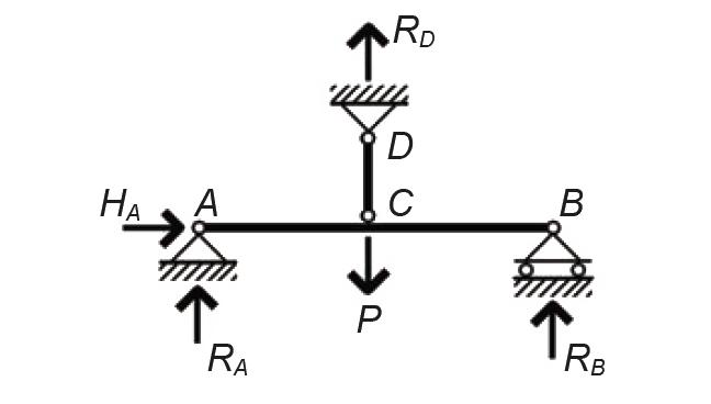
Where there are more reactions, or constraints, than there are equations of equilibrium, a structure is said to be statically indeterminate or redundant. Each added constraint adds one degree of indeterminacy or redundancy to the structure, making it that much more difficult to solve mathematically. To understand the basis of the mathematical solution to indeterminate structures, we will examine a simply supported beam with a single concentrated load that has been made 1-degree redundant (indeterminate) by adding a hanger at midspan: the structure now has four unknown reactions (constraints), and only three equations of equilibrium are available, as shown in Figure 1.46.
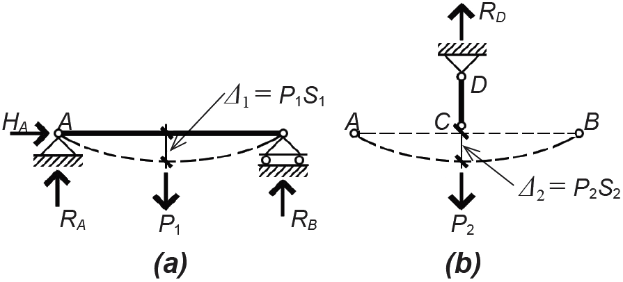
The key to the solution is to find an additional equation that includes one or more of the structure's constraint variables; that equation will not be concerned with equilibrium, but rather with the compatibility of structural deformations or deflections. Looking at the simply supported beam and the tension hanger separately, it is possible to write equations relating the loads acting on them to their deflection. For now, we will simply note that Δ1 = P1S1, and Δ2 = P2S2 as shown in Figure 1.47, where Δ1 and Δ2 are the deflections of the beam and hanger, respectively; P1 and P2 are the loads assumed to act separately on the beam and hanger; and S1 and S2 are deflection constants that include the length or span of the elements as well as their stiffness (i.e., their resistance to deformation).
These deflections, calculated separately for the beam and hanger, must actually be equal in the real structure, and the loads P1 and P2 that correspond to these equal deflections are actually only the parts of the total load, P, that the beam and hanger separately resist. In other words, Δ1 = Δ2; and P1 + P2 = P. This can be rewritten as follows:
Solving Equation 1.2 for P1 , and substituting the result into Equation 1.3, we get:
Solving for P2, we get:
Since the load P and coefficients S1 and S2 are all known, the force P2 can be determined from Equation 1.5. Then, from Figure 1.47b, it can be seen that the vertical reaction, RD = P2. With this "fourth" reaction solved, the other vertical reactions at A and B can easily be determined using the equations of equilibrium.
Equation 1.5 also clarifies the relationship between the element load-deformation constants, represented by S1 and S2, and the overall behavior of the structure. For example, if the constants are equal, it can be seen that P2 = P/2; i.e., half the load is resisted by the hanger and half by the beam. On the other hand, if S1 is small compared to S2 (i.e., if the hanger is more effective in resisting deformation than the beam), then P2 approaches the value of P, and the hanger begins to resist virtually all of the total load, with the beam's share approaching zero. This is of crucial importance in understanding the behavior of indeterminate structures: loads tend to follow the path of greatest stiffness, or, put another way, loads follow various competing load paths in proportion to the stiffness of those paths. In these formulations, "stiffness" is used as shorthand for the load-deformation relationship, which includes both the actual element stiffness (involving only material and cross-sectional properties) as well as element length or span.
For highly redundant structures, a greater number of equations, based on compatibility of deformations, needs to be solved simultaneously. While this becomes unwieldy if done by hand, structural analysis software has been developed to solve such problems: the designer need only indicate the geometry of the structure (including lengths and spans), the nature of each constraint (hinged, fixed, etc.), and the relative stiffness of each element. This last requirement presents a bit of a dilemma, since relative member stiffnesses must be assumed before the structure can be designed. The stiffnesses assumed for the structure determine how the structure will respond to its loads, unlike determinate structures, whose internal forces and moments are independent of member cross sections and material properties. For this reason, experience, trial and error, or a bit of both are crucial in the design of indeterminate structures.
Once internal forces and moments have been determined, however, the same strategies for the design of structural elements outlined in this book can be used, whether the structure is statically determinate or indeterminate.
© 2020 Jonathan Ochshorn; all rights reserved. This section first posted November 15, 2020; last updated November 15, 2020.