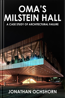
jonochshorn.com
Selected writings
Follow @jonochshorn
contact
Critique of Milstein Hall: Nonstructural failure

Jonathan Ochshorn

Tweet


Nonstructural failure contents: 1. introduction | 2. water and thermal control | 3. sloppy or dysfunctional details | 4. dangerous details | 5. maintenance issues | 6. cracks

6. Cracks

What follows is not an all-inclusive list of cracks in Milstein and Sibley Halls. I have not been given official access to such information, so the items that follow are based only on my random observations of the building:

  1. Concrete has a tendency to crack, simply because it shrinks when it cures. If the concrete is somehow restrained — prevented from shrinking — cracks will develop. On the other hand, if unrestrained, or subdivided with control joints, or properly reinforced, such cracking can be controlled. There has been extensive cracking of the topping slab in Milstein Hall (Figure 1), not only at "corners" without control joints, but also in the general field.

    Milstein Hall concrete slab crack

    Figure 1. The concrete topping slab at the upper floor plate of Milstein Hall has extensive cracks, both in the field and, as shown here, at re-entrant corners (photo by J. Ochshorn).

    The concrete slab of the bridge over the Crit Room space has also cracked, even with control joints present, presumably due to the complexity of its geometry (Figure 2).

    Milstein Hall concrete slab crack at bridge

    Figure 2. Cracks have appeared in the concrete slab of the bridge over the Crit Room space, in spite of control joints (photo by J. Ochshorn).

    Slab cracking has also occurred around basement columns where control joints were not properly detailed or constructed. Without properly detailed control joints to isolate the column from the rest of the slab-on-ground, the slab will crack — effectively creating its own "control joints" — since settlement of the slab will, in general, be smaller than settlement of the heavily-loaded column (Figure 3).

    Milstein Hall concrete slab crack

    Figure 3. Concrete slab-on-ground cracks have occurred around columns where control joints were not correctly detailed or constructed (photo and annotation by J. Ochshorn).

  2. Cracking has also occurred in the brick load-bearing walls of East Sibley Hall as a result of foundation underpinning (Figure 4).

    Figure 4. Video (1 minute long) by J. Ochshorn shows cracks in the brick wall of E. SIbley Hall due to underpinning of its foundations in order to excavate the foundation of Milstein Hall (video shot February, 2012; can also be viewed directly on YouTube).

    While no officially-sanctioned study of the causes of these masonry cracks has been made public, one plausible explanation is that inadequately-braced foundations, together with excessive vibrations from caisson drilling, contributed to the cracking (Figures 5 and 6). The century-old foundations of East Sibley Hall were underpinned by creating a new reinforced concrete foundation wall under the existing shallow foundation. However, no tiebacks were used to prevent lateral movement of this new wall, which runs in an east-west direction. Some combination of lateral thrust originating in the brick arches cut into the perpendicular (north-south) walls and from the mansard roof above, along with vibrations from the drilling of caissons immediately adjacent to this new wall, may have triggered these substantial cracks in the perpendicular masonry walls of E. Sibley Hall. That is, the entire north wall of Sibley Hall appears to have moved laterally towards the excavated Milstein Hall construction site, because (1) the arches in Sibley Hall already provided a discontinuity — a line of weakness — in the perpendicular bracing walls; (2) a horizontal force (thrust) was already present in those walls due to the action of the arches themselves as well as the geometry of the Mansard roof above; (3) the vibration of the masonry structure by caisson drilling facilitated the cracking of relatively weak brick mortar joints; and (4) the laterally-unbraced underpinned foundation wall was able to rotate on its footing since no horizontal tie-backs were provided.

    plans of Sibley Hall as built

    Figure 5. Original plans of E. Sibley Hall with large arches in brick bracing walls (highlighted in yellow) quite close to the north bearing wall adjacent to the future Milstein Hall construction site.

    section through Milstein and Sibley Halls

    Figure 6. Section through Milstein and Sibley Halls showing excavated area in front of underpinned foundation walls with possible rotation of foundations (shown in blue) causing cracking of the bracing walls in Sibley Hall (shown in red). Section annotated and edited by J. Ochshorn, based on Milstein Hall section on AAP website (accessed Aug. 27, 2013)

  3. Cracking has also occurred in the concrete wall of Milstein Hall under the cantilevered concrete slab that extends over an outdoor exit passageway below the loading dock just to the west of the main building (Figure 7). It's not clear what the cause of this crack is; possibly the wall is restraining the movement of the cantilevered slab above — to which it is attached — in ways that were unanticipated by the structural designers. After the adjacent retaining wall displaced by about 5/8 in. at the top, apparently causing a glass guard rail to shatter in May 2015, a more plausible explanation emerged. It seems that the retaining wall was actually tied to the adjacent building by horizontal reinforcement (this reinforcement became visible after movement of the retaining wall caused increased spalling of concrete in the building wall). For reasons that remain unclear, but possibly owing to corrosion of rebars where water seeps into the construction joint between the retaining wall and the building wall, the retaining wall failed to remain vertical as soil pressure pushed it out of alignment, causing both the shattering of the glass guard rail above, as well as increased concrete spalling in the adjacent building wall. My video (Figure 8) describes this process and shows the results of this building failure — a failure that may no longer be merely "nonstructural."

    crack in Milstein Hall concrete wall

    Figure 7. A rather serious-looking crack has occurred in a reinforced concrete wall terminating a concrete cantilever supporting the Milstein Hall loading dock.

    Figure 8. Video (3.5 minute long) by J. Ochshorn describes the possible interrelationship of guardrail glass shattering and concrete spalling at the intersection of the Milstein Hall loading dock and a reinforced concrete retaining wall (video shot May, 2015; can also be viewed directly on YouTube).

  4. The concrete wall below the guardrail was ultimately "repaired," with a sealant joint inserted between the two parts of the wall so that they could move independently. Inexplicably, however, the repaired guard rail above was re-constructed with a continuous metal trim over the glass, so that any movement in one side of the wall relative to the other would continue to cause problems. Such problems manifested themselves soon thereafter: these photos were taken in July, 2018, exactly at the spot of the prior failure.

    guard rail failure Milstein Hall 2018

    Figure 9. After it was "repaired," the guard rail failed again, since the metal trim at the top was made continuous, while the two sections of wall below were able to move independently (photo by J. Ochshorn, July 2018).

    guard rail failure Milstein Hall 2018

    Figure 10. Displacement of the two sections of the wall is evident where the glass guard rail meets the concrete (left); spalling and cracking of the concrete wall below has occurred, even after the "repair" (right) (photo by J. Ochshorn, July 2018).

[previous]


Nonstructural failure contents: 1. introduction | 2. water and thermal control | 3. sloppy or dysfunctional details | 4. dangerous details | 5. maintenance issues | 6. cracks