
Jonathan Ochshorn
© 2017 by the American Society of Civil Engineers, first published as "Revisiting Form and Forces: A Critique of Graphical Statics" in the Proceedings of the 2017 Architectural Engineering Conference, Oklahoma City, Oklahoma, April 11–13, 2017 (Edited by Jeffery S. Volz, Ph.D., S.E., P.E.).
Steel truss design calculator
ABSTRACT
Graphical statics is a clever, but cumbersome, set of procedures designed to represent the magnitude and distribution of structural forces or bending moments associated with various conventional structural forms (e.g., cables, vaults, beams, trusses) subject to external loads. At a time when digital computation did not exist and numerical methods could be labor-intensive and time-consuming, graphical statics provided a practical means for solving and refining commonly encountered structural problems. Although the methods are rarely used in contemporary engineering (or architectural) practice, their utility within architectural and engineering education is still being argued. Beginning with a brief historical summary, the current pedagogical rationale for graphical statics—that structural "form-finding" is central to architectural design; that one can abstract from issues of stability (improperly equating the formal consequences of tensile and compressive forces); and that structural forms should be efficient, elegant, and expressive—is critiqued.
INTRODUCTION
Graphics play an indispensable role in structural analysis. Virtually all structural problems are first represented graphically before being solved. In many cases, the geometry of structure and load is first "drawn" as a prerequisite to any further analysis. In other cases, results of testing or of theory are displayed in a graphical manner so that relationships and principles can be more clearly seen. For example, load-displacement or stress-strain relationships are often shown graphically, revealing important characteristics of material behavior that would otherwise be difficult to envision. Shear and moment diagrams display the distribution of force and moment over the span of a beam, so that not only maximum values can be easily found, but patterns of distribution can be understood quickly and clearly.
One historically important graphic application involves the solution of static equilibrium problems: graphical statics. The family of graphical statics methods can be extremely clever and can—in certain instances—reveal things otherwise difficult to see when using purely numerical methods. For example, the Cremona-Maxwell diagram shows not only the relative magnitudes of all bar forces in a determinate truss, but also indicates how those forces change when the truss geometry is altered. But there is also a downside: such methods may take something simple and truly elegant—three concise equations of equilibrium, for example—and turn it into something complex, idiosyncratic, and difficult to learn.
HISTORICAL ORIGIN OF GRAPHICAL STATICS
Carl Culmann (1821–1881) published Die graphische Statik in 1866 (with the first two chapters appearing in 1864), a book that "laid the foundation stone for graphical statics and graphical analysis" (Kurrer 2008, 317). Culmann was a fan of projective geometry as the basis of graphical statics, and criticized its subsequent development into an array of analytical tools (graphical analysis) in which the geometric basis of the force-form relationship became more obscure.
Of course, there were numerous other engineers and mathematicians who played a role in the development of graphical statics: more than a century before Culmann's book was published, the French mathematician Pierre Varignon (1654–1722) figured out graphical relationships between form and forces in his Nouvelle Méchanique ou Statique published posthumously in 1725. Figure 1a, which reproduces one of Varignon's diagrams, contains most of the essential elements of graphical statics: the two external loads shown in the lower "funicular" (form) diagram, K and L, are added together as the vertical forces E-F and F-G in the upper "force" diagram. Their relative magnitudes can be scaled off this diagram, as the ratio of their weights is uniquely determined by the geometry of the funicular cable, the slope of whose segments are mirrored in the sloping force components in the upper force diagram (shown as dotted lines).
Culmann extended the analysis of funicular cables to that of beams, recognizing that the calculation of reactions required only the addition of a "closing" line segment A-B in Varignon's funicular diagram and a parallel line in the force diagram that would divide the total external load into two appropriately scaled reactions, E-H and H-G. Culmann also realized that bending moments in such beams are proportional to the funicular shape of a cable under the same loads; the moment at any point is the vertical distance, n, multiplied by the horizontal force, L, scaled from the form and force diagrams respectively (Figure 1b).
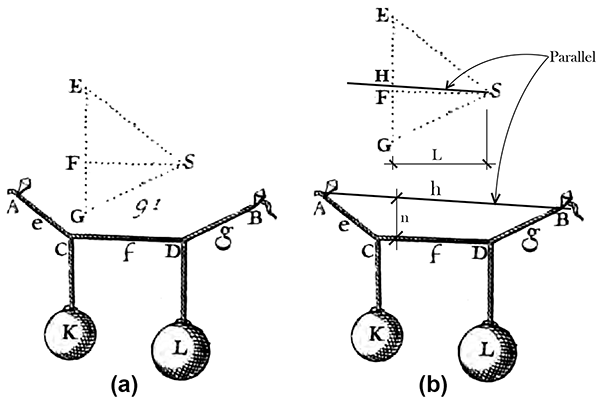
Figure 1. (a) Funicular polygon and force diagram from Varignon's Nouvelle Méchanique ou Statique, following p. 220 and (b) Varignon's diagram edited by the author (per Culmann) with added beam reactions and bending moments
Others, including William John Macquorn Rankine (1820–1872), James Clerk Maxwell (1831–1879), and Luigi Cremona (1830–1903) developed and refined a graphical statics method for determinate pinned trusses (the Cremona, or Cremona-Maxwell diagram is the most well-known of the graphical statics methodologies) using the same principles of correspondence between geometry (form) and forces. Graphical statics also had applications for the understanding and design of all sorts of arched and vaulted structures.
This collection of techniques for arches, beams, cables, and trusses, each with its own specific methodology, reached its highpoint in the last quarter of the nineteenth century, spurred in large part by the need for engineered trussed bridges to carry railroads across rivers and valleys. Yet by the early part of the twentieth century, according to Kurrer, the development of indeterminate framed structural systems in steel and reinforced concrete rendered this method increasingly obsolete (Kurrer 2008).
ADVOCATES OF GRAPHICAL STATICS
By the end of the first quarter of the twentieth century, sophisticated methods for solving indeterminate structural problems—including the force and displacement methods as well as the principle of virtual displacements—were developed, completing "the rise in the status of theory of structures through applied mathematics and mechanics" (Kurrer 2008, 37). Nevertheless, graphical analysis remained useful in practice, and was still being taught to engineering and architecture students. A textbook from 1921, Graphical Analysis (Wolfe 1921), lists several reasons for continuing to use graphical techniques rather than analytical methods: 1) to "save much time and labor," 2) to check the accuracy of results produced analytically, 3) to improve engineering judgment by better understanding "how the stresses act," and 4) to avoid the derivation and use of "complicated formulas."
Nearly one hundred years later, graphical statics has retained many advocates, especially in academia. Some contemporary academics are concerned that the possible link between "conceptual understanding and hand drawing" may be increasingly broken in engineering pedagogy, suggesting that "the optimal approach to strengthening both [visualization skills and conceptual understanding] may need to include a combination of computer and hand-drawing skills," thereby providing a "framework for design." Graphical statics, in their view, provides this important link (Baxter 2015).
Other writers reinforce this attitude, claiming that graphic statics is "still relevant in lecturing on structures. The clarity of the graphical method has a high didactic value, since interrelations and interdependencies, e.g. between structural geometry and forces, can be directly experienced visually" (Gerhardt 2003, 997). To demonstrate this contention, Gerhardt reproduces Cremona's diagram of forces in a truss, which "clearly illustrates how a reduction of the forces acting in the members of a framework [truss] can be achieved by increasing the depth of the trussed girder under consideration."
Perhaps the most comprehensive rationale for bringing graphical statics into academic curricula can be found in a textbook intended for both architecture and engineering students in their first year of structural education: Form and Forces (Allen 2010). The rationale articulated in this book has many interlocking components, and will serve as the primary vehicle for this author's examination and critique of the premises underlying the employment of graphical statics techniques as a pedagogical device.
ARGUMENTS AGAINST GRAPHICAL STATICS
It is true that Cremona's diagram "proves" Gerhardt's contention that "interrelations and interdependencies" can be made visible through graphical statics (Figure 2a). However, in relying on this truss diagram, the underlying moment equilibrium resulting from the action of vertical and horizontal forces is actually obscured. As an alternative to this approach, a free-body diagram of the same truss (Figure 2b) cut at mid-span—explicitly showing how external and internal forces are equilibrated—may well provide a better teaching strategy, since this latter diagram reveals in a more elegant way the relationship between the two equal and opposite force couples that cause internal stresses to decrease when the depth of the truss (or beam) increases. Moment equilibrium gives us a simple analytic equation (based on the forces and distances shown in Figure 2b): PL = FH. In other words, an increase in H must result in a decrease in F, for any given load, P, and panel length, L.
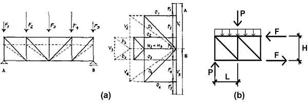
Figure 2. (a) Gerhardt's reproduction of Cremona's diagram of forces in a truss, comparing two trusses with different heights; and (b) free-body diagram of a truss showing resultant of applied load and reaction, P, along with internal forces in the chords, F (Figure 2b drawn by the author)
It is important to emphasize that this objection to the use of graphical statics is not based on the use of graphics—both the author's and Gerhardt's explanations rely on diagrams—but rather on the insistence that mathematical relationships between external and internal forces are somehow clarified by the use of graphical statics techniques.
Intuition and visualization. In Form and Forces, Allen claims that graphical methods "contribute to intuitive understanding and visualization of behavior..." (Allen 2010, xiii). First, leaving aside the question of "intuition," this claim implies that graphical methods are superior to numerical methods in fostering understanding and visualization of structural behavior. However, while graphical statics (see, for example, the Maxwell-Cremona truss diagram in Figure 2a), makes the relationship between geometry and force (or stress) visible, the causal relationship remains obscure. In general, graphical methods were devised and used as practical tools more than as windows into behavior. Before the advent of computers, structural engineers designing trusses, for example, could speed up the repetitive process of member design using graphical methods. Today, such methods would be (have been) replaced by structural analysis software.
It is also useful to examine exactly what intuition means in this context. It is certainly not the capacity to imagine a form, never before seen, that—through some mysterious mental process—turns out to represent an optimal, or efficient, arrangement of elements. Rather, intuition is an imprecise and inaccurate way to describe a capacity for creativity. Creativity never springs from nowhere: it is, in Le Corbusier's words, the result of a patient search. Felix Candela, writing about architects interested in devising unusual structures, echoes the same theme: "They appear to be convinced that there is no need to make any great effort—that a 'flash of genius,' a sudden inspiration, is quite enough to create a structure of novel and original conception. Unfortunately, the creative act is hardly ever the result of effortless inspiration. It is, instead, the—sometimes belated—result of long and painstaking work, the fruit of many years of constant effort and steadfast mental occupation with the problem concerned. That is, I very much fear, the only way to get the sort of inspiration that all ambitious young architects so ardently wish for" (Candela 1970, v).
Where mental processes leading to creative breakthroughs are hidden from consciousness, one might use the shorthand term "intuition," but such processes always have as their prerequisite countless hours of prior struggling (playing) with the material. This is what leads to structural—or any other form of—creativity: hours and hours of "playing" with the material. Whether one plays with graphical or numerical methods is not the key. Rather, it is the struggle itself—something often forgotten by authors of texts who themselves struggled with the material and thus gained some insight into it, but who believe they can short-circuit that process when it comes to their own students—that is the crucial and underlying element of all creativity.
Creation of "good" and efficient forms. "Graphical techniques are almost magical in their uncanny power to generate good form while finding forces simultaneously" (Allen 2010, xiii). The danger of teaching structures as "form finding" is that it places the discipline of structural engineering in competition with the ever-changing and always-subjective formal basis of architectural design. It also introduces a moral component into the design equation, something at once curious and inappropriate. David Billington, for example, invokes the specter of democratic ideals being "continually challenged by the claims of totalitarian societies" in order to explain "structural art" as a countermeasure that provides "evidence that the common life flourishes best when the goals of freedom [in the expression of a personal style] and discipline [in the search for efficiency and economy] are held in balance." This balance of freedom and discipline presupposes a designer who is "motivated by the conscious aesthetic search for engineering elegance" (Billington 1983, 5).
However, such idealistic attitudes ignore historical evidence that points to a different conclusion: in fact, architecture has often indulged in the extravagant use of resources (a cursory examination of the canonical works of architecture in any history of architecture text will bear this out), usually to lend support to owners of wealth and executors of power for whom the architecture is produced. It is hardly clear why structural design should be singled out as something frugal and efficient, when it only needs to be safe. And why is "elegance" sought, however that might be defined? Why shouldn't "clunky" or "chunky," or any other design conceit be equally valid in the subjective world of design and fashion?
For example, Rem Koolhaas describes the work of engineer Cecil Balmond in the following terms: "Instead of solidity and certainty, his structures express doubt, arbitrariness, mystery and even mysticism" (quoted in Sudjic, 2002). Balmond's own website (Balmond 2005) uses virtually the same words to describe his approach: "Toppling a tradition of Cartesian stability, informal reveals a process that allows for mystery, mysticism, doubt and fluidity, shifting the ground in engineering and architecture."
The notion that "efficiency" is a goal of structural design is quite dubious and somewhat superficial. On the one hand, a cable structure cannot be given a particular form in order to make it more "efficient" since its funicular shape is determined by loads and their placement along the length of the cable. Once these parameters are determined, any question of efficiency as a criterion in determining cable shape is moot. On the other hand, efficiency for other stable and predominantly axial-force structures—those capable of sustaining compression and tension (like trusses) or compression and bending (like arches or vaults)—is hardly a necessary goal of structural design, and its achievement, even where such a thing is desired, is hardly as self-evident a process as is implied. The question of efficiency will be examined in more detail below.
Focus on axial forces, abstracting from other issues. Even granting the notion that structures might be efficient, it is far from clear that minimizing forces, or even minimizing material volume, is always a useful measure of efficiency. But there is an even more crucial problem with such "form-finding" methods: by focusing on forces as a guide to form, graphical techniques make no distinction between elements in tension and those, in compression, subject to buckling (what the old graphical statics texts call "crippling"). Because the design of compressive elements often is independent of internal force (Euler's critical buckling stress is determined not by a material's allowable compressive stress, but by modulus of elasticity, radius of gyration, and effective length), it is illogical to assume that an optimal form can be determined from an analysis of forces in the class of structures where compression is present. Deflection is also an increasingly important consideration as materials get stronger—often governing the design of modern bending elements—that graphical methods take no account of.
This is made clear in Allen's chapter concerned with "Designing a Cylindrical Shell Roof" (Allen 2010, 65–91), where the belated acknowledgement of compressive buckling invalidates the initial (graphical) premise of the design process. This process unfolds as follows: First the funicular shape for a uniformly thick surface is given as a catenary, whose equation is not only not derived, but declared to be too "difficult to work with" (Allen, 2010, 65). Second, a parabola is recommended as a substitute geometry (and loads are computed as if the structure were perfectly flat). Third, these "horizontally projected" loads on the parabola are used to "generate... a second curve that is very close to a catenary" (Allen, 2010, 65). Fourth, the allowable stress for the reinforced concrete shell is set at "a rather low level so as to minimize the danger of buckling" (Allen, 2010, 71). Fifth, the thickness of the vault is found from the internal force and cross-sectional area, abstracting from considerations of compressive buckling, presumably since the "allowable stress" for the material has been reduced. Sixth, the calculated thickness is increased to provide adequate rebar cover and to account for the possibility of incorrect bar placement (tolerance). Seventh, the new thickness and its new weight are used to generate a new curved surface, this time accounting for the parabolic shape in the computation of actual—not horizontally-projected—weights.
However, the process is still not complete. After all this, the vault as designed is found to be pretty much useless, even after the vault thickness was increased—arbitrarily from a structural standpoint—to 140 mm (5-1/2 in.) to reduce the danger caused by bending stresses that were induced by new, or changing, load patterns (e.g., wind, seismic, construction, maintenance) and after having been told that this same increased thickness would "minimize the danger of buckling" (Allen, 2010, 71). But can a 140 mm (5-1/2 in.) thick vault spanning 61 meters (200 feet) really handle such bending stresses? This question is not systematically addressed. Instead, readers are warned that the 140 mm (5-1/2 in.) thickness is problematic due to the fact that the entire structure is in compression, and therefore potentially subject to buckling "at a load that is far below its theoretical capacity" (Allen, 2010, 77). Of course, without introducing a theory of buckling, it becomes possible to claim that the "theoretical capacity" of the vault is determined by its "allowable stress" rather than by its stiffness, and then act as if buckling is some sort of rogue proposition that challenges this "theoretical capacity," lowering it from what it should have been if only the "theory" had been obeyed.
Without recourse to either graphical or numerical methods, readers are directed to increase the effective vault thickness using stiffening ribs, "perhaps 25 to 35 ft [8 to 11 m] apart and reinforced fairly heavily" (Allen, 2010, 77). However, readers had been told before that lowering the allowable stress to 600 psi [4.1 MPa]—the premise upon which the entire design rests—would "minimize the danger of buckling." Why is the resulting structural form, already more than twice as thick to accommodate reinforcement and concrete cover, now considered dangerous? And how does such an explanation provide students with anything but a sense of bewilderment? At each and every step, it is only the all-knowing authorial voice that rescues this design problem from total disaster, while providing no logical rationale that could be applied to a different problem when the authorial expert is not present to say: "Now it's time to add a rib, or increase the depth," or any number of other things to make the structure more plausible. Students remain helpless and uninformed.
In other words, the method is not only long and more than a bit tedious, but it is essentially useless. One could get to the same place by just sketching something vaguely parabolic, dispensing with the entire charade of structural design, all the while knowing that one would find a structural engineer to work with to refine the concept in any real-world application. It isn't the idea of taking a catenary-like shape as a starting point for structural design that is at issue; in fact, a discussion of funicular shapes for common loading conditions is quite useful, whether accomplished by numerical analysis, graphical analysis, or physical modeling. The problem is that the requirement for students to learn all sorts of obscure and obsolete graphical analysis methods does not add anything to the initial insight that something like a catenary would be a good starting point for a vaulted surface. Once stiffener ribs are unilaterally added to account for bending in the vault surface—without any analytical justification at all—the whole premise of refining the initial approximation (still based on abstracting from bending and buckling stresses) becomes pointless.
Tool for analysis rather than design. Graphical methods are primarily tools for analysis rather than design, except in the sense that any analysis tool can be used to refine a design, and except for a very limited class of structures with almost no architectural applications (point-loaded cables and arches/vaults) where a "solution" actually emerges directly from the graphical analysis. The case of Robert Maillart is instructive in this regard, since it is well established that this brilliant Swiss engineer used graphical methods to refine his reinforced concrete bridge designs. However, his graphical methods were not design tools in the sense in which design is taken in Form and Forces, i.e., as a method for form-finding. Maillart already had a general idea for the appropriate structural form, and even for many of the formal refinements characteristic of his bridge designs, without recourse to graphical methods. He used the graphical methods not for "form-finding" but for "form-refining"; that is, to confirm and refine design assumptions already established. This is something that could be done just as well, if not better, using modern computational tools unavailable at the time, and is quite different from what architectural students ought to be doing when learning about structures. It is also quite different from, and should not be confused with, the creative insight that led Maillart to the innovative forms of his bridges.
Denis Zastavni, in his study of Maillart's design methods, confirms this point: "Our examination of the available design plans of the Salginatobel Bridge shows how early in the design process graphic statics are used by Maillart, and the fundamental difference in his appropriation of this tool when compared with Culmann's ideas. But what must be clear is that this approach presumes Maillart knew exactly how the entire structure would behave—depending on the kind of loadings—and that he knew which (kind of) forms had to be designed. It presupposes that he made up his mind beforehand on how to set concrete in its form depending on the particular circumstances of the structural issues within a complete structure" (Zastavni 2009, 1545, emphasis added).
Instructors should be giving architecture students insight into structural behavior, rather than obsolete and cumbersome tools that were once used to refine and confirm sizes of members and shapes of structures at a time when structural analysis software was not available. In most cases, refinement of structural form is not a useful objective for architecture students learning structures, since it hinges on rather subtle things (like loads and buckling) that require much more knowledge and experience than the architectural curriculum can support. Such exercises in refinement are precisely what architecture students should not be doing in a structures class, and it is precisely what graphical methods are (were) most useful for.
CASE STUDY OF OPTIMAL TRUSS DESIGN
The method for analyzing trusses using the Cremona-Maxwell diagram is probably the best known of the graphical statics techniques. The method does not account for buckling in compressive members, shear lag and bolt holes in the tension members, or deflection in the overall truss. For these reasons alone, it cannot be used to optimize the truss structure, where optimization is here defined as minimizing the volume of material required to carry a given load over a given span. In other words, any form that the graphical method "finds" will bear no relationship to the criteria of efficiency and economy. A graphical statics case study presented in Form and Forces (Allen 2010, 167) shows only that internal bar forces increase as the depth of the truss decreases, but can provide guidance neither for the optimal aspect ratio of span to depth, nor for the optimal number of panels (or for the optimal angle of the diagonal bars).
To show how the actual material properties of a steel truss affect its form, the author created optimization software for two common classes of trusses: Warren and Pratt (Figure 3). The trusses are designed using ASTM A36 double angles with equal legs according to recommended allowable strength design (ASD) procedures that account for buckling of compressive built-up double-angle members and the effective net area of tension members (AISC 2011). For specified span, spacing and distributed floor or roof loading, the software analyzes 105 truss variations; i.e., seven panel geometries (2, 4, 6, 8, 10, 12, and 14 panels), and 15 aspect ratios (span to depth) ranging from 2:1 to 16:1 to find the least weight (least volume) options. Deflection limits can be specified for both live load and total load and—for tension members—connections can be specified as welded or bolted (with bolt size also specified) and with any assumed value for the shear lag coefficient. Distributed loads are assumed to be resolved at the nodes of the top truss chord, i.e., applied to the truss by perpendicular spanning members fastened to the top chord of the truss at each pinned joint.
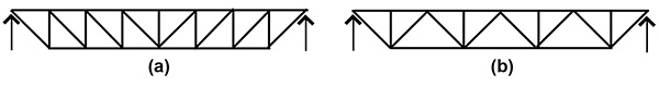
Figure 3. (a) Pratt truss and (b) Warren truss
An examination of trusses designed with various spans (and with spacing and distributed loads held constant) shows that no overarching "form" emerges for a simple truss. Instead, the truss geometry (i.e., aspect ratio and number of panels) takes on a range of values, depending on the particular conditions specified. Table 1 shows the optimal values of aspect ratio, diagonal bar angle, and number of panels for Warren trusses designed with spans ranging from 9 meters (30 feet) to 91 meters (300 feet). The truss spacing is set at 3 meters (10 feet), and roof loads are specified as 1.92 kPa (40 psf) dead load and 2.15 kPa (45 psf) snow load in this test. Deflection limits of span/180 for total load and span/240 for snow load were specified but had no impact on the results in this case.
TABLE 1. Optimal parameter values for Warren truss with fixed spacing and loads
| Span in meters (feet) | Optimal aspect ratio | Angle (degrees) of diagonal bars | Number of panels | Aspect ratios within 5% of optimal value |
| 9.1 (30) | 6:1 | 45 | 6 | 4:1 – 7:1 |
| 18.3 (60) | 8:1 | 45 | 8 | 7:1 – 9:1 |
| 36.6 (120) | 9:1 | 48 | 10 | 8:1 – 10:1 |
| 54.9 (180) | 10:1 | 50 | 12 | 9:1 – 12:1 |
| 73.2 (240) | 10:1 | 50 | 12 | 8:1 – 13:1 |
| 91.4 (300) | 11:1 | 52 | 14 | 9:1 – 11:1 |
The point of this exercise is not to draw any particular conclusions about the optimal design of trusses. Instead, what the results in Table 1 show is that optimal truss form, based on real materials and real material design constraints, is extremely sensitive to span and loads and cannot be abstracted from the effects of buckling in compressive bars and effective net area in tension bars. In other words, "form-finding"—the primary goal of pedagogical exercises based on graphical statics techniques—cannot be meaningfully applied to truss design using the Cremona-Maxwell diagram, since that diagram would generate essentially the same form and force diagrams (of course with forces increasing as loads increased) for each variation tabulated above, irrespective of the actual differences evidenced in the analytic investigation. The grounding of graphical statics in Jean-Victor Poncelet's projective geometry means that only the similarity of form and force diagrams is considered: using graphical statics, trusses of radically different spans therefore end up "finding" exactly the same form. The author's analytic optimization exercise, on the other hand, shows that the optimal aspect ratio for a truss actually increases as its span increases, revealing the limits of a graphical statics "form-finding" approach.
Attempts to salvage some type of optimization or form-finding protocol using graphical analysis end up simply importing unproven assumptions into the mix. For example, while it is possible to solve "for the nodal locations that give the desired force properties in a structure, such as a constant chord-force truss" (Beghini 2014, 356), such a strategy, in abstracting from buckling, shear lag, bolt holes, and deflection, cannot possibly render an optimal solution, even when wrapped in this rigorous-looking equation (Beghini 2014, 357):
![]()
Beghini equates minimal truss volume with the smallest possible sum of the product of area and bar length for each truss bar, where each bar area is found by dividing its bar force, Pi, by an assumed constant state of stress, σ. Yet finding the required area of a compressive bar by dividing its bar force by some fixed "allowable" stress abstracts from stability considerations; finding the required area of a tensile bar by dividing its bar force by this same "allowable" stress abstracts from any shear lag effect and any bolt holes that may reduce the capacity of certain steel bars used in trusses; and finally, focusing exclusively on the strength of truss elements abstracts from deflection considerations. Beghini's test case of a simple two-bar truss using a graphical method confirms that equal tensile and compressive allowable stresses generate a truss with 45° angles. When the allowable stress in compression is arbitrarily set at a value one-third that of the allowable stress in tension, the optimal truss angles change to 30° and 60°. Since the change in "optimal" angles of the truss bars reflect changed assumptions about allowable stress, the results are described as a "methodology for form-finding of trusses graphically" (Beghini 2014, 356). However, because there is no logical basis for the assignment of arbitrary ratios of allowable compressive and tensile stress, the use of graphical analysis in such tests actually produces no meaningful results.
CONCLUSION
Graphical statics is a clever, but cumbersome, set of procedures designed to show the magnitude and distribution of structural forces or bending moments associated with various conventional structural forms (e.g., cables, vaults, beams, trusses) subject to external loads. At a time when digital computation did not exist and numerical methods could be labor-intensive and time-consuming, graphical statics provided a practical means for solving and refining commonly encountered structural problems.
Graphical statics is not, however, a "form-finding" methodology, since it abstracts from actual material behavior (compressive buckling; tensile shear lag; and deflection) in establishing a projective equivalence of form (geometry) and force. The author's analytic truss optimization software demonstrates that precisely those factors that are ignored by graphical statics play a crucial role in determining actual optimized form.
Now that graphical statics has become largely obsolete as an analysis tool within professional practice, it is being resurrected as a design (form-finding) tool within architectural and engineering curricula. What is not clear, however, is whether the time and effort required to master the multitude of graphic techniques—a different method for each type of structural form—has any relationship to the creative application of structural concepts and structural systems to architectural forms. This is true not only because graphical statics abstract from the effects of compressive buckling, tensile shear lag, and structural deflection, but also because many structural forms are either entirely routine (e.g., consisting of regularly spaced columns, girders, beams, and slabs) and therefore subject to ordinary rules of thumb within a preliminary design process rather than complex graphical (or numerical) analysis; or, at the other extreme, because they are complex, irrational, unique, and idiosyncratic.
REFERENCES
AISC (2011). Design Examples: Version 14.1, American Institute of Steel Construction, February 2013 revision.
Allen, Edward et al. (2010). Form and Forces: Designing Efficient, Expressive Structures, John Wiley & Sons, Hoboken, New Jersey.
Balmond, Cecil (2005) "Informal" website (accessed at http://www.balmondstudio.com/work/informal.php).
Baxter, Sarah C., Johnson, Ann, and Fralick, Bethany S. (2015). "Revisiting Graphical Statics," 122nd American Society for Engineering Education Annual Conference & Exposition, Paper ID #11374, Seattle, Washington.
Beghini, Lauren L., Carrion, Juan, Beghini, Alessandro, Mazurek, Arkadiusz, and Baker, William F. (2013). "Structural optimization using graphic statics," Structural and Multidisciplinary Optimization, 49/3, Springer-Verlag Berlin Heidelberg, 2014
Billington, David P. (1983). The Tower and the Bridge: The New Art of Structural Engineering, Basic Books, New York.
Candela, Felix (1970). "Foreword," in Roland, Conrad, Frei Otto: Tension Structures, Praeger Publishers, New York.
Gerhardt, Rolf, Kurrer, Karl-Eugen, and Pichler, Gerhard (2003). "The methods of graphical statics and their relation to the structural form," Proceedings of the First International Congress on Construction History, ed. S. Huerta et al.
Kurrer, Karl-Eugen (2008). The History of the Theory of Structures: From Arch Analysis to Computational Mechanics, Ernst & Sohn, A Wiley Company, Berlin.
Sudjic, Deyan (2002). "Take a bow, Mr Balmond," The Guardian (accessed at http://www.theguardian.com/books/2002/oct/27/art).
Wolfe, William S. (1921). Graphical Analysis: A Text Book on Graphic Statics, McGraw-Hill Book Company, New York.
Zastavni, Denis (2009). "What Was Truly Innovative about Maillart's Designs Using Reinforced Concrete?" Proceedings of the Third International Congress on Construction History. NEUNPLUS1, Berlin.
First posted 13 April 2017; last updated 13 April 2017