
Jonathan Ochshorn
© 2016–2018 Jonathan Ochshorn.

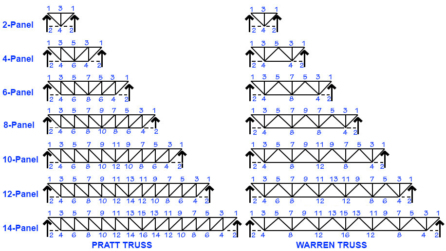
Directions: Enter values in yellow fields: choose Warren or Pratt truss (see Figure 1 for explanation of node labeling); enter aspect ratio and number of truss panels; enter values for span, spacing, loads, and so forth.
Press "update" button at the bottom of this page.
Trusses are designed using ASTM A36 double angles with equal legs according to recommended allowable strength design (ASD) procedures that account for buckling of compressive built-up double-angle members and the effective net area of tension members per AISC, Design Examples: Version 14.1, American Institute of Steel Construction, 2011, February 2013 revision. Bar forces are computed based on the assumption that truss bars are "pinned," and that uniformly-distributed roof or floor loads are applied at the joints of the top chord. Governing load combinations are determined based on ASCE Minimum Design Loads for Buildings and Other Structures (ASCE/SEI 7-10). Deflection limits can be set for live load and total load. This calculator does not design the bolted or welded connections between bars; when bolted connections are selected, it is assumed that the net area of the section is reduced by 1 line of those bolts. The dead load selected includes the weight of the truss.
Explanations and examples of buckling in compressive elements and shear lag (and effective net area) in tension elements can be found in my text.
Disclaimer: This calculator is not intended to be used for the design of actual structures, but only for schematic (preliminary) understanding of structural design principles. For the design of an actual structure, a competent professional should be consulted.
First posted August 23, 2016 | Last updated March 19, 2018