
Jonathan Ochshorn
© 2013–2016 Jonathan Ochshorn.

Directions: Enter values in the yellow fields for "units and criteria," "material properties," "geometry," "loads," "moment values," and "number of rebars" (bars) as well as the bar size for slab reinforcement.
Press "update" button.
The calculator computes required steel area and selects bars (or spacing) for 1-way slabs, T-beams, and columns. Columns are designed based on the number of occupied floors selected. Bar fit is not checked by this calculator. See Table A-5.3 in the text (2nd edition) for bar fit limits. "Cover" for slab and beam reinforcement is here defined as the distance from the outer face of the concrete to the centerline of the reinforcing bar or bars. In other words, subtracting this cover dimension from the slab or beam thickness gives the effective depth. Both the beam and girder width refer to the "stem" width below the slab, and not the effective width of the T-beam. Required steel for girders is not computed.
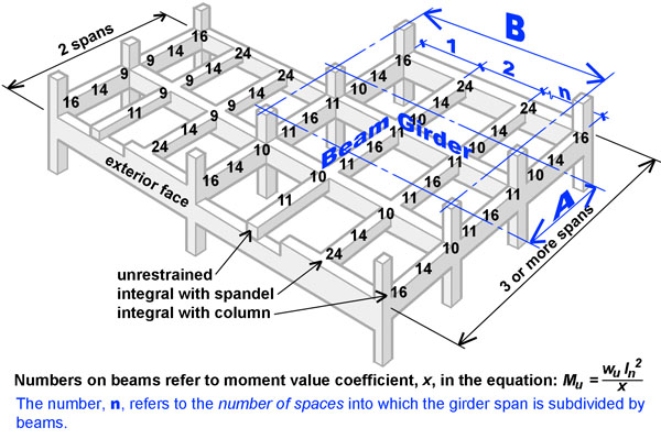
Calculations and results, shown below to the left, are based on Building Code Requirements for Structural Concrete (ACI 318-14) and Minimum Design Loads for Buildings and Other Structures (ASCE/SEI 7-10). For T-beams and 1-way slabs, criteria for the use of moment values must be met; for columns, it is assumed that buckling is not an issue, i.e., that the ratio of height to minimum cross-sectional dimension is no greater than about 12. "Interpolated" R-ρ calculations give exact solutions; use the "tabular" setting to check answers based on approximate tabular values found using Table A-5.9 in the text (2nd edition). Dead load is automatically calculated based on the selected weight of reinforced concrete; except that column weight is excluded from column dead load. Beam and girder spans, A and B, are measured to centerlines; calculator uses specified beam and girder thicknesses to establish clear span dimensions. To find stirrup spacing, insert computed value for "Maximum shear force for beam at face of support, Vu" into stirrup spacing calculator. "Number of spaces" is defined as n in Figure 1 above. For the structure shown in Figure 1 with beams at the third points of the girder, n = 3. For beams at the quarter points, n = 4, etc. Floor beams and slabs are designed based on dead and live loads; roof beams and slabs are designed based on dead loads plus the greater of snow or roof live (maintenance) loads. When the "number of occupied floors above column" is set to zero, the slabs and beams will be designed based on dead and roof loads. Otherwise, the beams and slabs will be designed based on dead and live loads. Columns are designed based on the governing combined loads (considering dead, live, roof live-maintenance, and snow loads per ASCE/SEI 7-10), as summarized in Table A-2.7 of the text (2nd edition).
Lateral forces and lateral force-resisting systems are not considered in this calculator.
More detailed explanations and examples can be found in my text.
Disclaimer: This calculator is not intended to be used for the design of actual structures, but only for schematic (preliminary) understanding of structural design principles. For the design of an actual structure, a competent professional should be consulted.
First posted May 9, 2013 | Last updated February 29, 2016