
11. SLOPPY OR DYSFUNCTIONAL DETAILS
Detailing failures are not inevitable, even in complex or peculiar buildings like Milstein Hall. There is, however, a higher probability that such design problems will occur when complex or peculiar buildings are produced and, for that reason, more attention must be paid in both the design and construction phases to avoid them. By analogy to "defensive driving" techniques employed to reduce automobile accidents, architects should always employ "defensive detailing" to reduce the likelihood of sloppy or dysfunctional details.
As buildings get more complex, more collisions of geometries and of materials can be expected; each potential collision must be investigated and resolved. Anticipating problems means understanding architecture as something in motion rather than as a fixed and static object—i.e., to think of buildings as objects to be inhabited rather than merely modeled or photographed. Everything moves: structures move under dead, live, and environmental loads; elements expand and contract due to thermal and moisture changes; while water, vapor, air, and heat flows make the building enclosure a virtual laboratory of physical and chemical changes. Defensive detailing simply means that the unanticipated must, instead, be anticipated.
Unintended entomological display case
Milstein Hall's roof beams and corrugated steel deck are exposed in the upper-level studio space, but the second-floor structure is mostly covered up by stamped aluminum soffit panels. Where a rectangular hole was punched through this floor structure to accommodate an egress stair to the lobby below, glass fascia panels were installed along the edges of this opening to reveal parts of the steel structure that would otherwise have been hidden, creating what amounts to a structural display case (fig. 11.1).
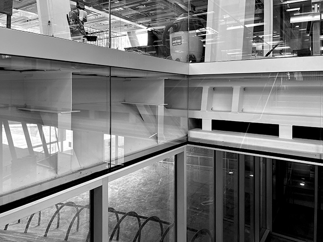
Figure 11.1. Glass panels at the second-floor stair opening create what amounts to a structural display case.
Although very little additional insight into the building's structure can be gleaned by looking through these glass panels, something unexpected can be seen. The spaces between these glass panels were neither sealed nor covered with vertical mullions, creating numerous access points for moths and other insects and arachnids. They get in, but cannot find their way out, and so this glazed area has inadvertently become more of an entomological than a structural display case (fig. 11.2).
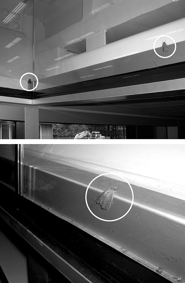
Figure 11.2. Moths and other insects and arachnids get in, but cannot find their way out, and so this glazed area—that reveals Milstein Hall's floor steel structure at the rectangular cut-out for the main entry (and egress) stair—has inadvertently become something of an entomological display case.
Sloppy details at the second-floor auditorium entrance
There are many ways to characterize nonstructural building failure. One type of nonstructural failure comes about because of the difference between drawing or modeling something and actually building something. It may seem obvious that representation and reality are different, yet this difference is often ignored when architects design buildings. As discussed below in terms of room geometry, many products are manufactured as extrusions (aluminum sections, for example), or are rolled or otherwise molded into straight elements. In some cases, such elements can be bent (drywall and steel rolled sections, for example), but in many cases, building components manufactured in straight sections cannot easily be reconfigured into curved geometries. Even intersections of straight elements that are not at right angles can cause problems.
In Milstein Hall, most sloppy details are at the intersection of straight elements, probably because—aside from the cast-in-place concrete dome structure—there are not that many curved elements in the design. The glass enclosure providing an entrance from the upper-level studios to the auditorium below is an example of a sloppy and seemingly ad hoc transition where straight elements are joined (fig. 11.3).
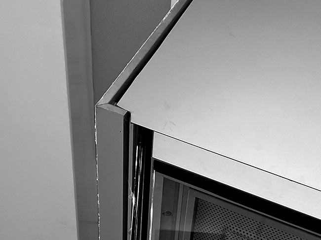
Figure 11.3. Metal panels come together awkwardly at the angled enclosure providing an entrance from second-floor studios to the auditorium below.
It's not completely clear why this detail should have presented such complications until one searches in the working drawings for an indication of what was intended. While there are detail sections through the front of the enclosure and elevations of the front and side panels, there are no drawings that show how the front and side elevations are reconciled—i.e., how the two surfaces come together at this corner.
Metal panels are similarly mistreated within the same enclosure, where the steel Miesian "box" meets the auditorium stair carved into the concrete "blob" (fig. 11.4).
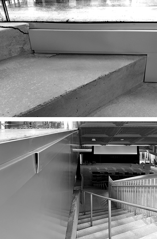
Figure 11.4. Metal trim creates an awkward transition between the Miesian "box" of the second floor and the concrete "blob" that includes auditorium stairs.
Even abstracting from the poor condition of the concrete itself, detailing of the metal trim in relation to the concrete stair seems entirely ad hoc and awkward—as if so much intellectual effort went into framing the conceptual juxtaposition of box and blob that no further thought was available for its implementation. And, as bad as the metal trim is, the concrete itself, along with the sliding door seal, also seem to be self-destructing at the same entrance to the auditorium, from the second-floor studios (fig. 11.5).
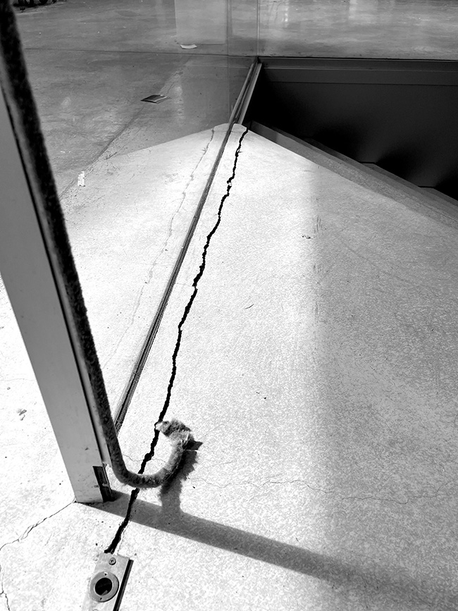
Figure 11.5. Major concrete slab cracking has occurred at the second-floor entrance to the Milstein Hall auditorium; the acoustic seal for the sliding door is also falling apart.
Metal cover plate and cladding issues
There are many other examples of poorly detailed metal plates that have come apart or delaminated in Milstein Hall, both inside and outside the building. On the outside, a number of curtain wall sill cover plates are no longer functioning as intended (fig. 11.6).
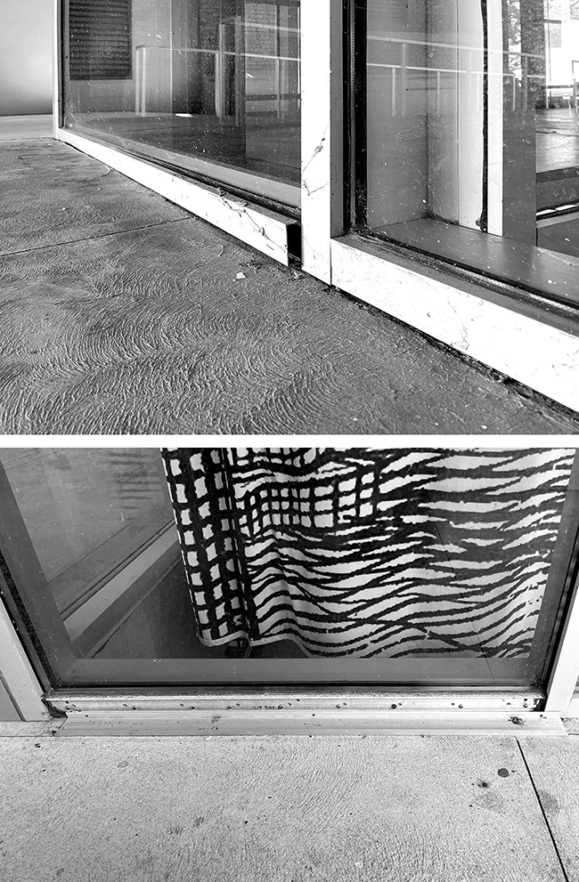
Figure 11.6. Curtain wall sill cover plates have partially or completely detached at the north side of Milstein Hall's lobby (top) and at the west side of the auditorium (bottom).
On the inside, some poorly detailed metal cladding has delaminated, near the exterior stair exit door on the second floor (fig. 11.7), although it appears to have been eventually glued back in place.
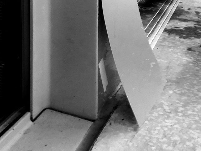
Figure 11.7. Poorly detailed metal cladding has delaminated near the exterior stair exit door on the second floor.
Glass guard aluminum trim problems
And then there are the aluminum trim pieces at the top edge of all those exterior glass guards that seem to be coming apart at their joints (fig. 11.8).

Figure 11.8. Aluminum trim pieces at the top edge of exterior glass guards are coming apart at their joints.
The aluminum trim pieces for interior glass guards are doing a bit better, but are still hardly perfect; over time, the mitered joints for the guards at the second-floor stair opening have also opened up (fig. 11.9).
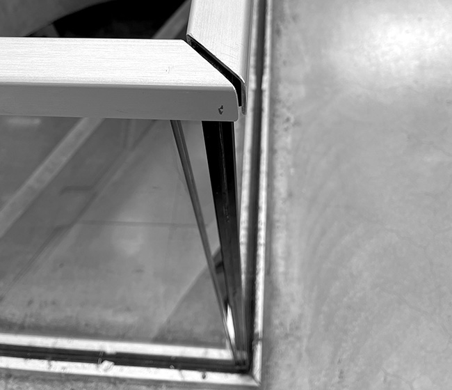
Figure 11.9. Aluminum trim at the top of interior guards in Milstein Hall, like the exterior trim, is also coming apart at the seams.
Cracks in concrete slabs
Concrete has a tendency to crack, simply because it shrinks when it cures. We've already seen how this has manifested itself in Milstein Hall's bathroom (fig. 2.2). If the concrete is somehow restrained—prevented from shrinking—cracks will develop. On the other hand, if unrestrained, or subdivided with control joints, or properly reinforced, such cracking can be controlled. There has been extensive cracking of the topping slabs in Milstein Hall, not only at "corners" where stress concentrations could be expected (fig. 11.10), but also in the general field fig. 11.11). The fact that there are no control joints anywhere on the second-floor slab—neither in the underlying structural corrugated steel and concrete deck nor in the 2-inch (51 mm) topping slab—may have contributed to this problem, in spite of the welded-wire mesh that was placed in both slabs.
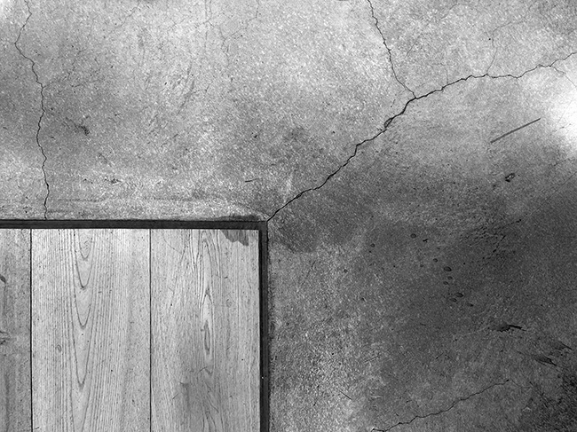
Figure 11.10. Cracks have proliferated throughout the topping slab on the second floor of Milstein Hall; especially at corners—here, where the wood floor area meets the concrete.
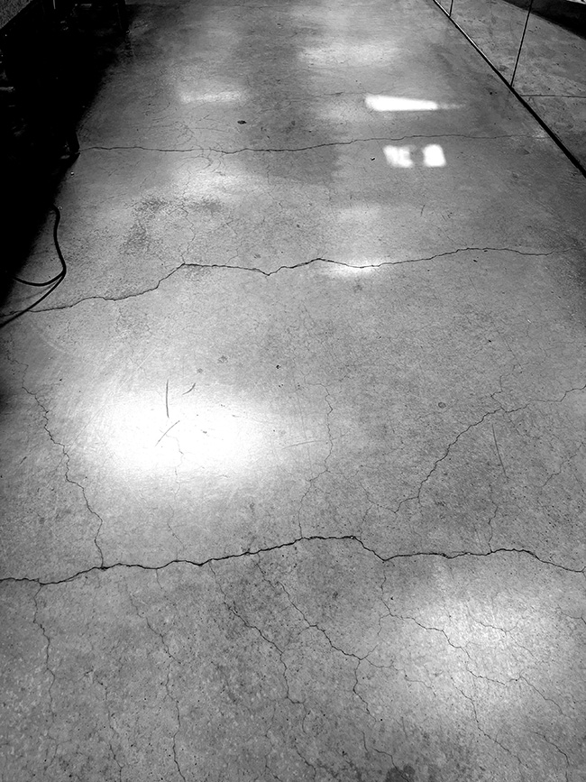
Figure 11.11. Cracks appear not only at re-entrant corners of Milstein Hall's second-floor slab, but also throughout the general field.
Slab cracking has also occurred around basement columns where isolation joints were not properly detailed or constructed. Without properly detailed joints to isolate the column from the rest of the slab-on-ground, the slab will crack—effectively creating its own "control joints"—since movement of the slab will, in general, be different from movement of the heavily-loaded column (fig. 11.12).
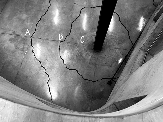
Figure 11.12. Concrete slab-on-ground cracks have occurred, not only in the general field, but especially around columns where control joints were not correctly detailed or constructed. Concentric cracks around a column in the Crit Room have been highlighted at A and B, while neither the "aesthetic" circular control joint around the column at C, nor the orthogonal grid of sawcut control joints aligning with the centerline of the columns, proved effective at controlling cracks.
While control and movement joints are routinely placed in exterior pavement and sidewalks, the presence of cracks in that context is fairly common, in part because such surfaces are placed directly on grade, with less attention paid to preparation of the underlying substrates, and less control over the potentially expansive properties of soil, the presence of unruly tree roots, and other such things. Nevertheless, the cracking of pavement at the corner of Milstein Hall's exterior column (fig. 11.13) is far more predictable and preventable, by using the same sort of isolation joints that should have been used in Milstein Hall's basement spaces.
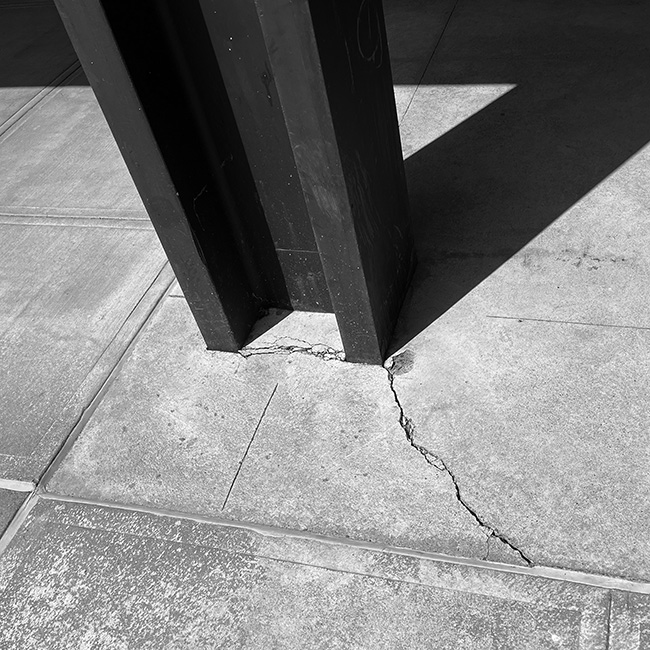
Figure 11.13. With no isolation joints at exterior columns, slab cracking is fairly predictable.
Cracks in brick walls
Cracking has also occurred in the brick load-bearing and cross-bracing walls of East Sibley Hall (fig. 11.14). While no officially sanctioned study of the causes of these masonry cracks has been made public, one plausible explanation is that inadequately tied-back underpinned foundations, together with excessive vibrations from caisson drilling, contributed to the cracking.
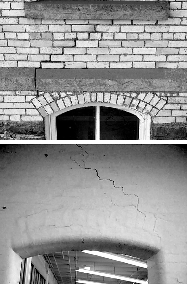
Figure 11.14. Cracking in the brick walls of Sibley Hall occurred after the foundations of Sibley Hall were underpinned and the Milstein Hall site was excavated.
During the construction of—and excavation for—Milstein Hall, the century-old foundations on the north side of East Sibley Hall were underpinned by creating a new reinforced concrete foundation wall under the existing shallow foundation. This was necessary because the excavation for Milstein Hall was so deep, relative to the bottom of the Sibley Hall footings, that Sibley Hall itself would have become destabilized without extending the existing foundations deeper into the earth. However, no tiebacks were used to prevent lateral movement of the new underpinned foundation wall for Sibley Hall, so they were able to rotate in a northward direction—toward the excavation created for Milstein Hall (fig. 11.15).
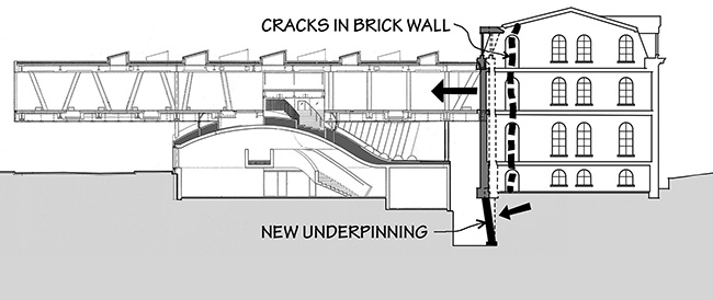
Figure 11.15. Section through Milstein and Sibley Halls showing excavated area in front of underpinned foundation wall with assumed rotation of foundation underpinning causing cracking in the bracing walls of Sibley Hall.
Some combination of lateral thrust originating in the brick arches cut into the perpendicular (north-south) walls of Sibley Hall and from its Mansard roof above, along with vibrations from the drilling of caissons immediately adjacent to this new wall, may have triggered these substantial cracks in the perpendicular masonry walls of East Sibley Hall. In other words, the entire north wall of Sibley Hall appears to have moved laterally towards the excavated Milstein Hall construction site, because (1) the existing arches in Sibley Hall's perpendicular brick cross-bracing walls already provided a discontinuity—a line of weakness; (2) a horizontal force (thrust) was already present in those walls due to the action of the arches themselves as well as the geometry of the Mansard roof above; (3) the vibration of the masonry structure by caisson drilling facilitated the cracking of relatively weak brick mortar joints; and (4) the laterally-unbraced underpinned foundation wall was able to rotate on its footing since no horizontal tie-backs were provided.
Retaining wall displacement
A glass guard separating Milstein Hall's loading area from an accessible ramp shattered, due in part to a series of bad design decisions (fig. 11.16). The accessible ramp behind the retaining wall was built to link the parking lot at West Sibley Hall to Milstein Hall's basement entry doors below the loading area. This ramp slopes downward along the basement wall of West Sibley Hall, continuing its slope along the basement wall of Sibley Dome, at which point one can enter Milstein Hall at the basement level. On the side of the ramp opposite Sibley Hall, a reinforced concrete retaining wall separates the ramp from the parking lot. However, precisely when the ramp reaches Sibley Dome, the concrete retaining wall ends and Milstein Hall's loading area begins, below which is a basement storage area and corridor with a concrete and glass wall facing the ramp. The glass guard is situated on, and spans over, the top of these two walls—the concrete retaining wall at West Sibley Hall and the concrete basement wall at Sibley Dome—providing a necessary barrier at the edge of the parking lot and loading area.
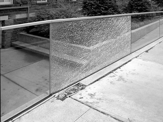
Figure 11.16. A glass guard separating Milstein Hall's loading area from an accessible ramp shattered in 2015.
The retaining wall, which holds back soil beneath the parking lot, was not part of the original Milstein Hall plan. Instead of the current surface parking, the original plans, approved by the City of Ithaca's Planning and Development Board in early 2009, called for "a parking garage that will provide 199 spaces, with two underground levels accessible from Central Avenue and one surface level accessible from University Avenue."1 This proposed structured parking lot would have been more like an underground building, negating the need for a retaining wall at the edge of the ramp, but it was cut from the project because of budgetary concerns stemming from the financial crisis of 2008. The retaining wall—added to the project when the parking garage was eliminated—was structurally connected to the underground storage room and corridor wall at the western end of Milstein Hall, beneath the loading area.
A retaining wall would typically be completely separated from an adjacent building with some sort of isolation joint since the wall and building behave quite differently under lateral loads: the retaining wall must resist lateral soil pressure as a cantilevered structure fixed at its footing, whereas the building's basement-foundation wall is braced laterally by its ceiling—the concrete deck of Milstein Hall's loading area in this case—and is not subject to lateral soil pressure at this location. As soon as the retaining wall was connected to the concrete wall of Milstein Hall, lateral pressure on the retaining wall was transferred, through its structural connection, to Milstein Hall's basement wall and caused the basement wall to crack (fig. 11.17).
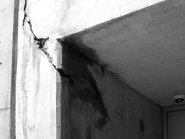
Figure 11.17. A large crack appeared in Milstein Hall's basement-foundation wall immediately adjacent to the concrete retaining wall to its left, shown here in 2013.
The precise mechanism of failure became clearer two years later, in 2015, when the glass guard immediately over this cracked foundation wall shattered. The top of the retaining wall displaced approximately 0.75 inches (19 mm) relative to the position of Milstein Hall's basement-foundation wall, dragging the glass guard with it. However, this particular glass guard panel—inexplicably—had been constructed so that it spanned over the joint between the retaining wall and the building wall, thereby being restrained by the building as it was being displaced by the retaining wall. Something had to give, and, unsurprisingly, the glass shattered (fig. 11.18 left). The concrete crack that had emerged shortly after the building was constructed was not, apparently, taken as a sign of potential structural danger and over the following two years, the lateral soil pressure continued to push on the retaining wall, leading ultimately to this failure. It is also possible that spalling of the concrete and widening of the crack was triggered, not only by lateral soil pressure on the retaining wall, but also by water, with road salt, working its way through cracks in the concrete and corroding the horizontal reinforcing bars that were placed between the retaining wall and the building (fig. 11.18 right).
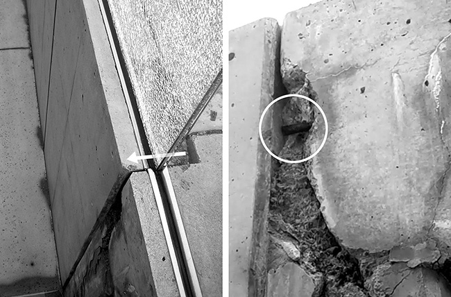
Figure 11.18. The glass guard panel between Milstein Hall's loading area and the accessible ramp from the parking lot (left), shown here in 2015, can be seen spanning over the joint between the displaced retaining wall and the building; spalling of the concrete could also have been triggered by corrosion of reinforcement, visible in the highlighted circle, placed between the retaining wall and the building (right).
Ultimately, the shattered glass panel was replaced, but problems remain. Figure 11.19 (top), from 2023, shows that continued relative movement between the two walls seems to have caused the aluminum trim at the top of the guard to displace; figure 11.19 (bottom left), from 2018, shows that a gasket at the bottom of the glass guard panel had detached from the U-shaped shoe holding the glass in place. This same image shows a sealant joint between the retaining wall and the building, but my guess is that the two walls remain structurally connected. And the underlying problems with water, and possibly road salt, entering the wall continue to cause efflorescence in 2023 (fig. 11.19 bottom right), even after all the cracks and spalled concrete have been patched up.
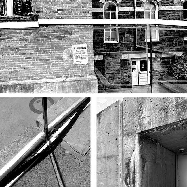
Figure 11.19. The glass guard panel between Milstein Hall's loading area and the accessible ramp from the parking lot, shown here with displaced trim in 2023 (top), a detached gasket in 2018 (bottom left), and continued efflorescence in 2023 (bottom right).
Aluminum gridded guard failure
Milstein Hall's stepped auditorium was designed and constructed with aluminum gridded guards at its edges (fig. 11.20 top). This design quickly proved inadequate—the guards were apparently too flexible and unstable— so they were removed and replaced in January 2012 with painted steel guards—having a similar gridded design—just a few months after the building was occupied (fig. 11.20 bottom).
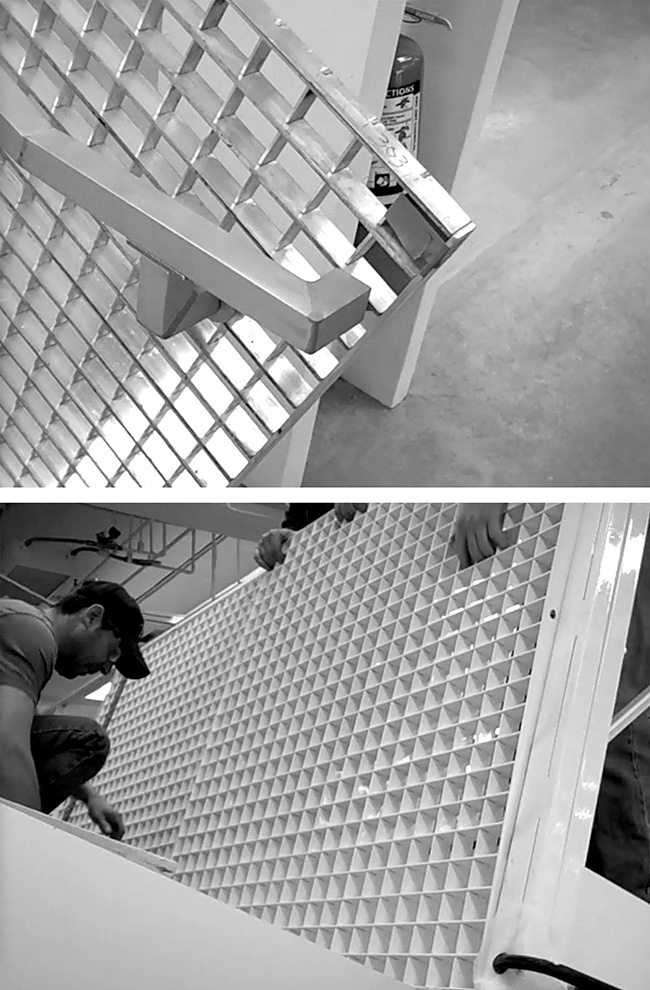
Figure 11.20. Milstein Hall's original aluminum guards were apparently too flexible (top) and were replaced with welded steel guards having a similar gridded design (bottom) just a few months after the building was occupied.
Cupping of wood floor boards
"Cupping" of wood floorboards occurs due to differential expansion or contraction on the top and bottom faces of the boards. If the wood grain is not perfectly consistent (where such perfection is found only in the finest quarter-sawn lumber), moisture will have a different effect on the two faces, as these faces will differ in the degree to which their grain is oriented radially rather than tangentially—wood expands and contracts more tangentially than radially. It is possible that, even with the wood grain perfectly consistent throughout the cross section, moisture will be present to a greater or lesser degree where the boards are in closer contact with moisture, either from the underlying concrete slab, or from the air above the boards. Since wood expands or contracts depending on its moisture content, which is in turn sensitive to atmospheric conditions, any such exposure to moisture may cause cupping or its opposite—crowning—of the boards. Furthermore, this effect is more pronounced with wide boards such as the ash planks specified for Milstein Hall (fig. 11.21) since the warping of the boards occurs over a greater cross-sectional dimension. In any case, the issue seems to have been largely resolved with sanding and refinishing of the floor in the summer of 2023.
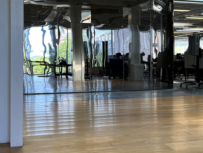
Figure 11.21. The wide ash planks in Milstein Hall's wood floor have cupped, i.e., warped so that the center of each board is lower than its edges, due to differential moisture conditions above and below the wood surface. When light strikes the floor obliquely, the curved surface of the boards creates a repeating pattern of light and shadow. The stainless-steel-clad wall in the background is Milstein Hall's second-floor electrical closet.
Mottling of concrete surfaces
There have been several instances of unintended concrete staining, or mottling, on Milstein Hall's walls and floor slabs. In the case of the floor slabs, a red stain appeared in the Crit Room, possibly caused by wooden protection boards that were placed over the slab before it was fully cured. In the case of exposed concrete walls, also in the Crit Room as well as the auditorium, mottling or staining apparently resulted from the combination of two form release agents that were applied to wooden forms (fig. 11.22). The field Superintendent for the general contractor, Welliver, put it this way:
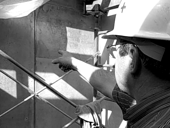
Figure 11.22. The contractor's field superintendent explains the mottling of concrete surfaces in Milstein Hall's Crit Room.
We experienced a little problem on this wall here with two form-release agents reacting. That's why we've got the mottling, the odd color, and then it looks like staining. That's what we determined it was: a release agent that was on the plywood previously, compared to what was specified and put on. And we ended up with these dark stains that you see on the corner there. It actually changed the texture of the concrete. So in an attempt to unify the whole thing, we're trying to use an acid wash which is a masonry cleaner with the acid in it to try to blend and bleach out the dark color.2
In some cases—not necessarily, but quite possibly, in this instance—the specification of LEED-friendly, but relatively untested, products may have contributed to these unintended problems.
Notes
1 Dani Neuharth-Keusch, "Ithaca Board Grants Final Approval For Milstein Plan," Cornell Daily Sun, Jan. 28, 2009, here.
2 Mike Fulkerson, Field Superintendent for Welliver (general contractor) transcribed from the author's video. See Jonathan Ochshorn, "Milstein Hall Nonstructural Failure: Concrete Staining," here.