
2. FLEXIBILITY
Millard doctrine
Where a space is designed to be appreciated aesthetically as a single entity—think of the Sistine Chapel in the Apostolic Palace in Vatican City or the Main Concourse of Grand Central Station in New York City—such a space can only be changed by doing violence to the design. In Milstein Hall, virtually all of the spaces (compartments) have this quality: the auditorium and the Crit Room are designed explicitly as idiosyncratic sculptural volumes—figural elements—whose geometry is essentially fixed forever.
Bill Millard explains the rationale for such a strategy in the works of OMA by arguing that "the most striking feature of a building must now be the one that all the more mundane features require, the one whose subtraction would demolish the structure. Beauty that also solves problems is free to remain beauty."1 Such an attitude may well succeed in getting one's beautiful building built without compromise, but it simultaneously forecloses the possibility of flexibility when critical building compartments (e.g., Milstein Hall's Crit Room and auditorium) cannot be altered except with great difficulty. I have described in chapter 16 how the requirement for a new exit from the concrete-domed Crit Room necessitated the literal demolition of reinforced concrete walls to create an egress passage through the auditorium. That this new exit created acoustical "bridges" between the Crit Room and the auditorium—making it difficult to use both spaces simultaneously because sounds generated in one space interfere with the activities in the other space—demonstrates another way in which flexibility is constrained in this building. Stewart Brand has described this phenomenon as follows:
Institutions aspire to be eternal, and they let that ambition lead them to the wrong physical strategy. Instead of opting for long-term flexibility, they go for monumentality, seeking to embody their power in physical grandeur. Post offices, colleges, and state capitals belie and hinder their high-flux information function with stone walls, useless columns, and wasteful domes. The building tries to stand for the function instead of serving it.2
Shearing layers
Architectural flexibility can mean adaptation as an ongoing operating condition of the building, but is more generally understood as the ability to anticipate and facilitate future change.3 All buildings must adapt to the future, a future in which some changes are quite predictable—even if their precise content is unclear (e.g., replacement of furniture, painting of walls and ceilings, repair or maintenance of interior and exterior construction, upgraded appliances and mechanical equipment, and so on)—and in which some changes are unexpected and, at least when the building is designed and built, unknown. On the other hand, some buildings must also adapt to ongoing changes as part of their utilitarian functionality: this includes many museums, where new exhibits may well require reconfigured partitions or newly painted walls.
But all buildings change, whether or not these changes are anticipated by their designers. Stewart Brand quotes the British architect Frank Duffy, who prefers to think of buildings, not as "buildings," but rather as "several layers of longevity of built components," categorized as shell, services, scenery, and set (fig. 2.1).
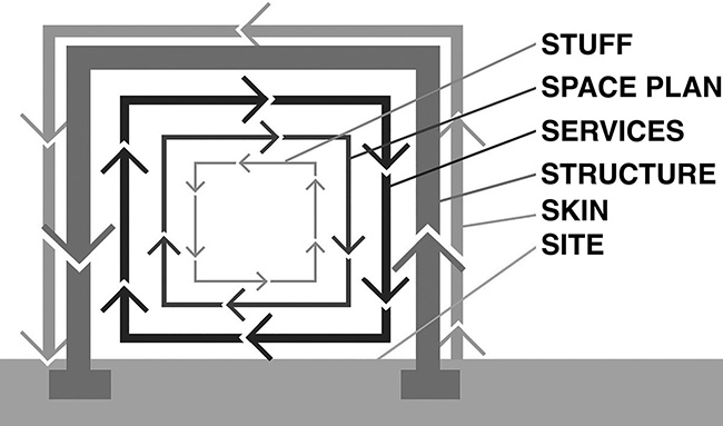
Figure 2.1. Stewart Brand's revised diagram of time-based building systems, based on Frank Duffy's categories, but with two more S's and some changed names ("site, structure, skin, services, space plan, and stuff"), each with its own characteristic time-frame for repair, maintenance, or replacement.
In this formulation, the shell, or structure, ought to survive for the life of the building, whereas services (like HVAC systems) might last 15 years, scenery (such as suspended ceilings or partitions) might last 5–7 years, and set (primarily furniture) may well be moved around or replaced far more frequently.4 "Thinking about buildings in this time-laden way is very practical," says Duffy. "As a designer you avoid such classic mistakes as solving a five-minute problem with a fifty-year solution, or vice versa."5
Instead of designing buildings that explicitly account for the timebased functions diagrammed by Brand and Duffy, architects often invoke a literal (and short-sighted) ideal of functionalism that fixes in place, and formally articulates, some current idea about the requirements of, and relationships among, specialized rooms and circulation systems, thereby foreclosing the possibility of adapting to future programmatic changes. Critiquing the work of architects Hugo Häring and Hans Scharoun in the 1920s, the German critic and historian Adolf Behne anticipated precisely this problem, arguing that the articulation of different corridor widths in their buildings, based on a biological analogy of "living arteries" that are allowed "to narrow, to shrink, in places where there is less traffic" was actually dysfunctional:
This is all right provided that traffic always follows this same path until the death of the building; that the same conditions prevail as on the first day; in the same way as is the case for blood corpuscles in an organism. But it is wrong, and the functional becomes antifunctional as soon as the traffic finds different conditions— such as through a change of owner or when purpose alters traffic requirements—whereby it could be heaviest in precisely those places where the plan requires it to be lightest.6
On the other hand, even accepting the critique of Behne and the advice of Duffy, it's hardly self-evident how to make buildings truly flexible, since both culture and technology change in ways that simply cannot be predicted.
Integration of mechanical, electrical, and plumbing into structure
Where mechanical, electrical, plumbing, sprinkler, or lighting systems are designed for one specific spatial geometry, it can be difficult to alter or subdivide such a space. In the case of Milstein Hall, the foolishness of such specificity and fixity has been taken to an extreme. Even the bathrooms have been turned into inflexible and bespoke interlocking puzzle pieces which cannot easily be modified. Specifying built-in stainless-steel urinals that terminate in a cracking (and therefore noncompliant) concrete floor slab7 cannot even be called foolish—perhaps the word "unfathomable" would do it justice (fig. 2.2).
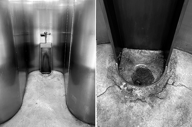
Figure 2.2. Stainless steel urinals in Milstein Hall are built into the noncompliant (cracking) concrete floor slab and cannot easily be repaired or replaced.
Even the "adaptable and open floor plan"8 on the second-floor studio level cannot be easily subdivided or partitioned, not only because the space was explicitly designed to be understood as a single entity and to have no interior partitions, but because lighting, fresh air, heating, and cooling systems are all designed for a single open space. As but one example, fresh air is brought into the space through special ducts, triggered by CO2 sensors that are placed in several zones within the larger space. Any newly partitioned room would therefore have no way to control the provision of fresh air unless a CO2 sensor happened to be in that space. But, even in that case, fresh air would also be supplied throughout the entire zone controlled by that particular sensor, irrespective of where the partitions were placed. The same type of zoning, but with different zones than those designated for the fresh air supply, determines the provision of heat (using radiant heating in the floor slab) in the winter and coolness (using so-called chilled beams hanging from the ceiling) in the summer (fig. 2.3).
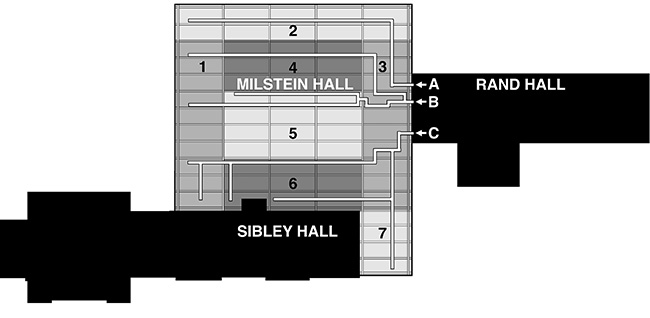
Figure 2.3. The second-floor studio space is subdivided into three zones for
fresh air distribution, originating in a mechanical room placed on the third
floor of Rand Hall (labeled A, B, and C); and divided into seven zones for heating and cooling
(labeled 1–7).
Furthermore, because this ductwork was threaded through holes in the webs of the structural beams, and because the system as a whole was designed for a large, undivided space, it becomes extremely difficult to modify, since a new pattern of ducts and sensors would not necessarily fit through the holes in the beam webs that were designed specifically for only one possible configuration (fig. 2.4)
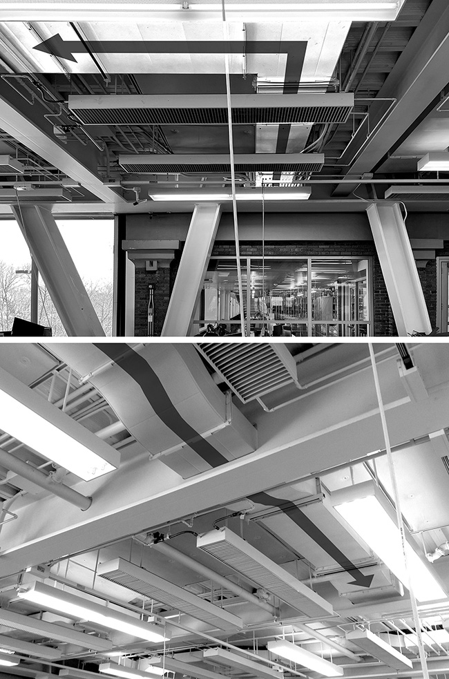
Figure 2.4. A duct for outside air distribution—labeled "A" in figure 2.3—is shown emerging from adjacent Rand Hall, where the mechanical room is located one level above (top). These ducts carrying fresh air are threaded through the webs of structural steel beams (bottom), making future alterations difficult. Light fixtures and matching chilled beams can be seen just below the ducts. Illustrative arrows added by the author.
And like the fresh air system, the zoned heating and cooling systems cannot be reconfigured in any future subdivision of the second-floor studio space without essentially destroying the building (fig. 2.5).
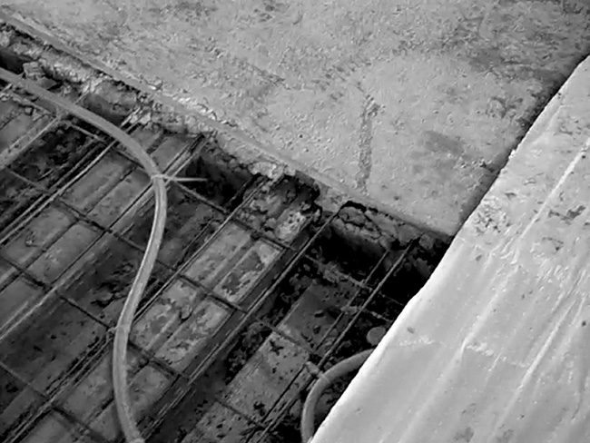
Figure 2.5. Radiant heating tubes are embedded in the structural concrete floor deck of the second-floor studio space.
This issue of embedding mechanical, plumbing, and so on within the structural elements of the building is pervasive in Milstein Hall, a classic error that locks "quick" systems within "slow" ones, making maintenance, repair, replacement, or more comprehensive changes extremely difficult. Stewart Brand puts it this way: "An adaptive building has to allow slippage between the differently-paced systems of Site, Structure, Skin, Services, Space plan, and Stuff. Otherwise the slow systems block the flow of the quick ones, and the quick ones tear up the slow ones with their constant change."9
Aside from the ducts providing fresh air, and radiant heating tubes embedded in the floor slab, fire sprinkler pipes and electrical conduits are embedded within concrete slabs, ducts for the auditorium are buried under concrete slabs-on-ground or built into the auditorium seating structure, and stormwater drainpipes are embedded between the double concrete faces of the Crit Room dome. In the Crit Room itself, lighting fixtures are carved into the concrete surface, so that their dimensions and locations are fixed forever and conduits that provide them with power are inaccessible—buried within the concrete. The structure of the dome itself needed to be thickened by the depth of these lighting fixtures in order to provide adequate concrete cover for the bottom reinforcement bars, since the cover which ordinarily would have been provided at the bottom of the dome was compromised by the slots in the concrete cut out for the recessed light fixtures (fig. 2.6).
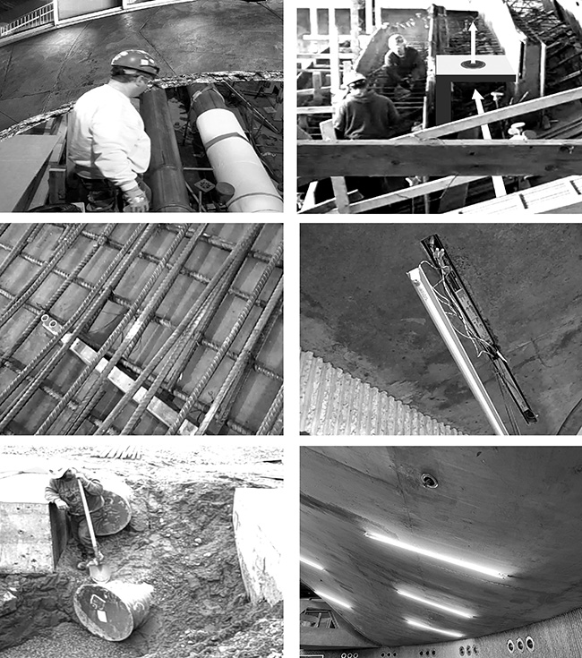
Figure 2.6. Mechanical, electrical, and fire safety items buried within structure: storm drainpipes within concrete dome (top left); conditioned air plenum within concrete seating structure in auditorium (top right); lighting fixture cutouts in the Crit Room dome placed in formwork (middle left); cutout in dome concrete, (middle right); mechanical ducts below slab-on-ground (bottom left); and sprinkler pipes embedded in concrete ceiling above Crit Room and elsewhere (bottom right).
Complex and curved formal elements, like Milstein's dome, need not have been cast in concrete. The same geometry and expression can be achieved with less material, less money, and a greater ability to avoid conflicts between the structure and the building's electrical, mechanical, fire safety, and plumbing services. The Broad, an art museum in Los Angeles designed by Diller Scofidio + Renfro, achieves an equally complex formal expression of curved surfaces using plaster on lath—a technique often used in traditional construction—thereby avoiding all the constructional and functional complications seen in Milstein Hall (fig. 2.7).
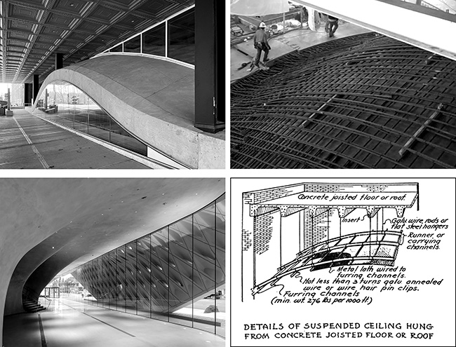
Figure 2.7. The Broad Museum (bottom left) creates a complex curvature using lightweight metal framing, plaster, and lath, similar in principle to traditional plaster techniques (bottom right); while Milstein Hall's dome achieves a similarly complex curvature (top left), but with far greater cost and complication, using cast-in-place reinforced concrete (top right).
Notes
1 Millard, "Banned Words."
2 Brand, How Buildings Learn, 44.
3 This section is adapted from Ochshorn, "Flexibility and its discontents."
4 Frank Duffy, quoted in Brand, How Buildings Learn, 12.
5 Frank Duffy, quoted in Brand, How Buildings Learn, 17.
6 Behne, The Modern Functional Building, 129.
7 "In other than dwelling units, toilet, bathing and shower rooms floor finish materials shall have a smooth, hard, nonabsorbent surface. The intersections of such floors with walls shall have a smooth, hard, nonabsorbent vertical base that extends upward onto the walls not less than 4 inches (102 mm)." ICC, "1209.2.1 Floors and Wall Bases," in Building Code, 2020.
8 "Milstein Hall: Built to Inspire."
9 Brand, How Buildings Learn, 20.