Jonathan Ochshorn
Water analogy. By analogy to water, electricity is said to "flow," from negative to positive charge. The difference in charge is measured in volts (V = electromotive force). The amount of current is measured in amperes or "amps" (A = current) which is constrained by the resistance of the wire (Ω = resistance measured in ohms — using the Greek letter "omega").
Ohm's law. The fundamental relationship between these terms is Ohm's Law, which states that the current is proportional to the force divided by the resistance (I = E / R) where the current, I, has amp (A) units; the electromotive force, E, has volt (V) units; and the resistance, R, has ohm (Ω) units.
Impedance. Most electrical devices are not quite this efficient, losing a bit more power due to something called "inductive resistance." The total of the resistance and this inductive resistance is called the impedance (Z), which is also measured in ohms. The equation thus becomes: (I = E / Z) where the current, I, has amp (A) units; the electromotive force, E, has volt (V) units; and the impedance, Z, has ohm (Ω) units.
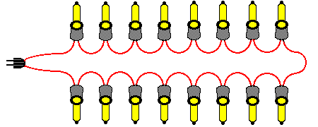
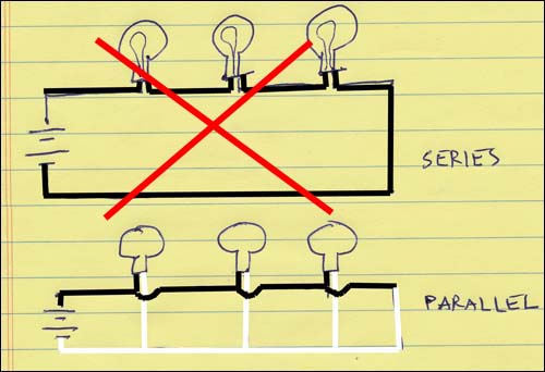
Appliances are not generally placed in series.* Appliances are not placed in series (one after the other) but rather in parallel. In series, one blown-out lightbulb would kill power throughout the whole series. That's why a fuse or circuit breaker is always wired in series.
In series, the current (I) must be the same in all appliances.
However, the individual resistances of the appliances may vary and the total resistance is the sum of the individual resistances.
The current can therefore be written as I = VT / (R1 + R2 + ... + Rn).
For that reason, individual voltages vary for appliances in series, with the voltage at each appliance being equal to the current, which is constant, times the individual resistance of the appliance.
* An exception occurs where strings of small lights are placed in series; when one goes out, the whole string of lights goes out.
Appliances are placed in parallel. Placing appliances in parallel leaves the voltage intact, while increasing the needed current (amperage), since the total resistance actually decreases compared to the individual resistances of each appliance: For parallel circuits, the total resistance, RT = 1 / (1/R1 + 1/R2 + ... 1/Rn). The current differs for each appliance, depending on its resistance, since the voltage is constant for all appliances, with the total current equal to the sum of the individual currents. A fuse or circuit breaker, placed in series in such a parallel circuit, is designed to limit the total current (amperage), and will shut down the circuit if the maximum amperage (current) is exceeded. Typical household circuits are rated at 15 or 20 amps.
Alternating current. Most commonly encountered electricity uses alternating current (AC) rather than direct current (DC). In the US, the direction of the current cycles at a rate of 60 changes per second, or 60 hertz (Hz). This creates some inefficiencies when used to power low-voltage direct current devices such as computers, which require some sort of integral power supply to handle the conversion.
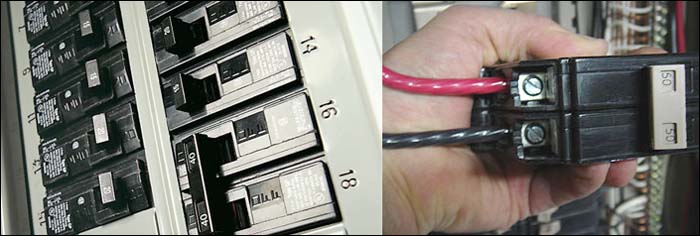
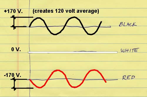
Voltage measurement. The voltage is determined by the differential between the electromotive force at the two ends of the "battery": typical electric service, at least at the residential or small building scale, supplies three wires: two "hot" wires (black and red) are at 120 V. The third "neutral" wire (white) is at 0 V (because it is connected directly to the earth). When we combine either of the hot wires with the neutral wire, we get a difference of 120 V. This is the normal voltage in the US. However, since the two "hot" wires are 180 degrees out of phase (on purpose), they can be combined to create 120 + 120 = 240 V. service. This is useful for things that need lots of juice, like clothes dryers. A typical panel box alternates the "red" and "black" hot wires so that a double circuit breaker can be easily connected to the red and black wires for 240 volts.
Big buildings may have higher voltages to run things with big motors or large electric needs (e.g., elevators, water heaters).
Power and energy. The unit of electric power is the Watt (W) or, more commonly, the kW = 1000 W.
The power is equal to the force times the current, so that:
W = E x I = volts x amps.
Power (watts) = rate at which energy is used = energy / time.
So the measure of electrical energy = power x time = kWh.
Example: How much current is drawn by a 100 W light bulb at 120 V? Since power = force x current, we get:
100 = 120 x A; or A = 100 / 120 = 0.82 amps.
Can 10 such bulbs be placed on a single 15 amp circuit? Since each bulb draws 0.82 amps, 10 bulbs draw 0.82 x 10 = 8.2 amps. This is less than the capacity of a 15 amp circuit, so it works.
Circuits/ wiring. Most household circuits are rated at 15 or 20 amps. Some appliances (kitchen, bathroom, air conditioners) require their own circuit, since they draw so much current.
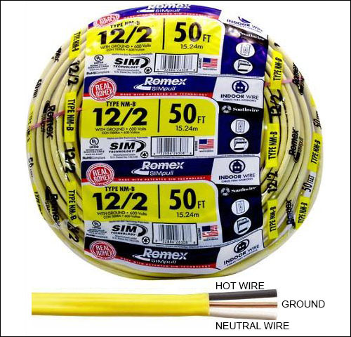
US wire sizes get smaller as the numbers get bigger: 12 AWG (american wire gauge) is common; 14 AWG was often used for smaller loads; the size of circuit breakers corresponds to the size of wire.
Protecting the copper wire is commonly a plastic or rubber casings (nonmetallic sheathed cable, or "Romex").
In most larger buildings, such wire is placed in conduits.
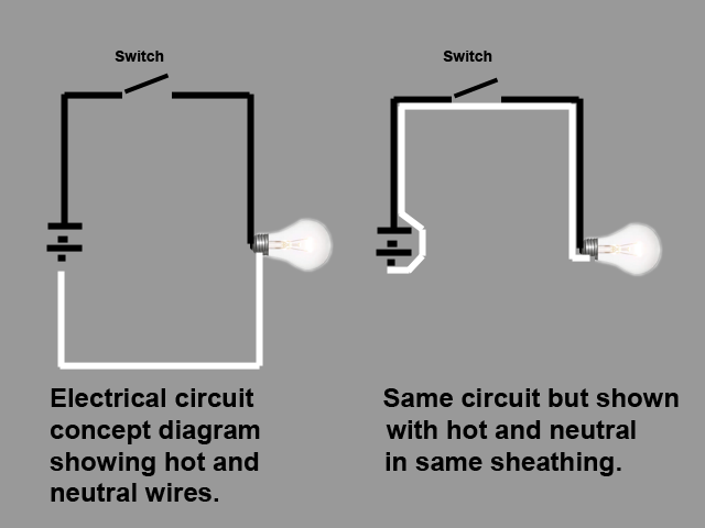
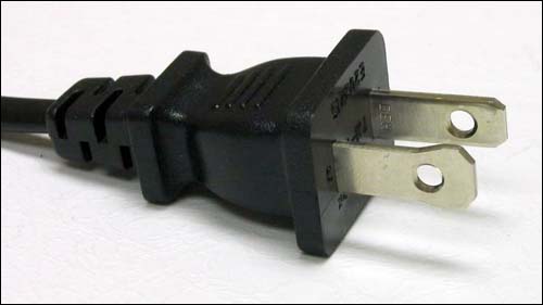
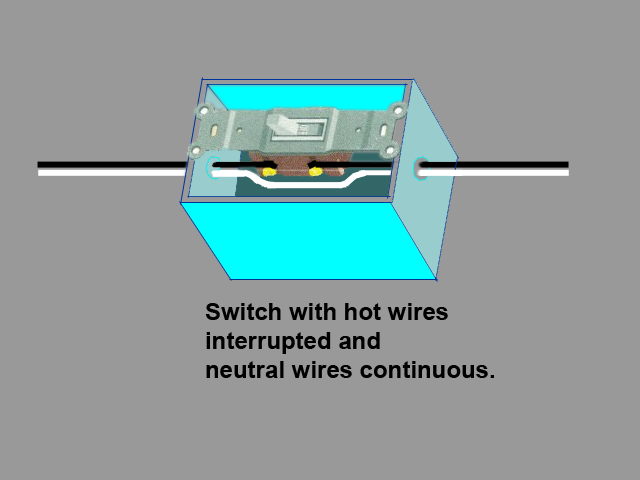
Switches are always placed in the "hot" wire, so that off really (mostly) means off. This only works consistently if the plugs are "polarized" so that they only fit into the outlets one way— this is why modern plugs have two different sizes for the two prongs.
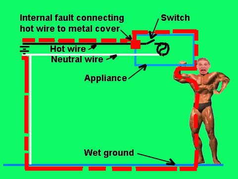
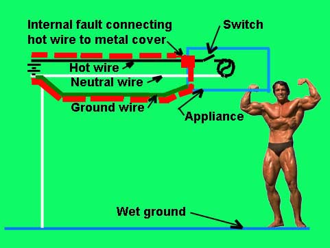
Grounding. An appliance ground (that extra unsheathed wire) guards against unintended shorts within the appliance that could direct current through the human touching the appliance. Three-prong plugs connect any conductive material on the appliance to the ground wire, which prevents the metal cover from maintaining a charge.
Ground fault interrupters (GFI or GFCI) have an added precautionary device that measures whether any current is moving where it shouldn't—these are mandated where wet conditions (kitchens, bathrooms) could create a serious ground path through a defective appliance.
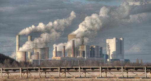
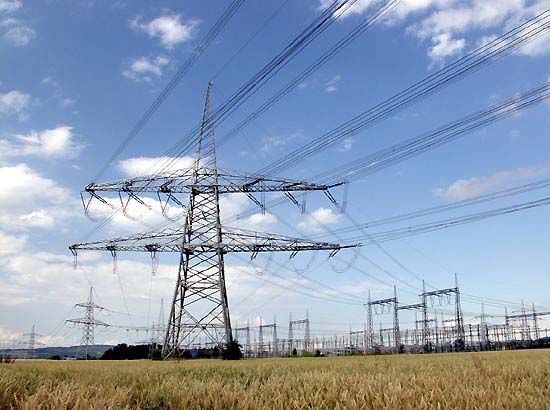
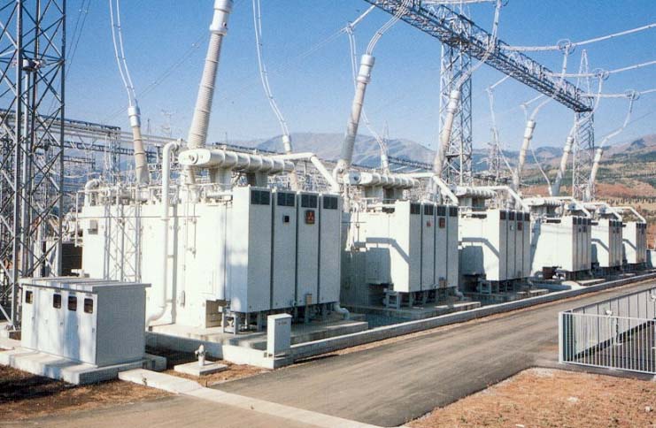
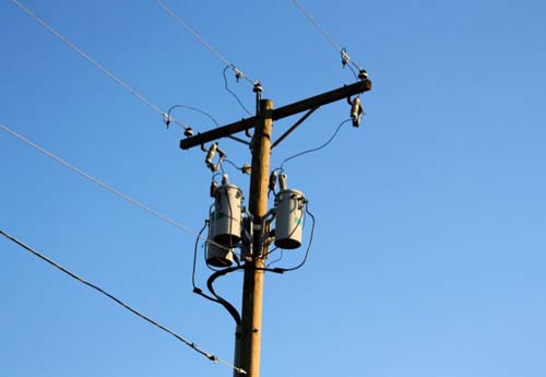
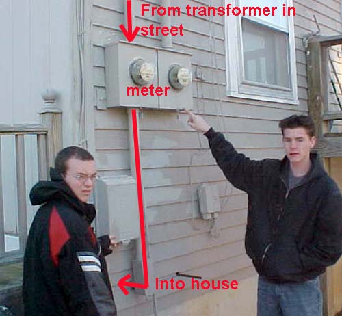
Distribution. Electricity starts with production of power by generators at 5,000 volts, stepped up to as much as 1,000,000 volts where distances are great; stepped down to 10,000 volts for overhead lines in streets; stepped down to building voltage in "service transformers." Goes to meter; then into the building where it is connected to a panel box with a main circuit breaker. Within the panel box are numerous smaller-amp circuit breakers; each circuit supplies power to a series of plugs or lights. Usually, plugs and lights are not combined on a single circuit so if a power surge from a plugged appliance trips a circuit, the lights stay on.
In larger buildings, the same general arrangement occurs, but on a larger scale. A service transformer may be placed outside or inside the structure in a ventilated vault. It supplies the regular 120 volts, but also various other voltages for things like large motors (elevators), lighting, etc. to an electrical room or closet. There, switchgear controls and distributes the power to various panel boxes placed around the building.
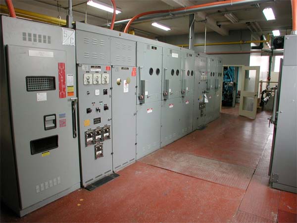
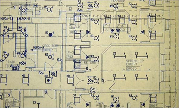
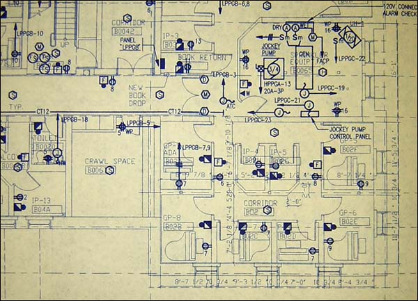
Images showing a typical distribution network follow:

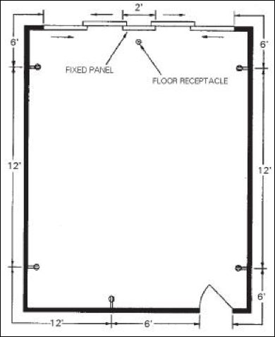
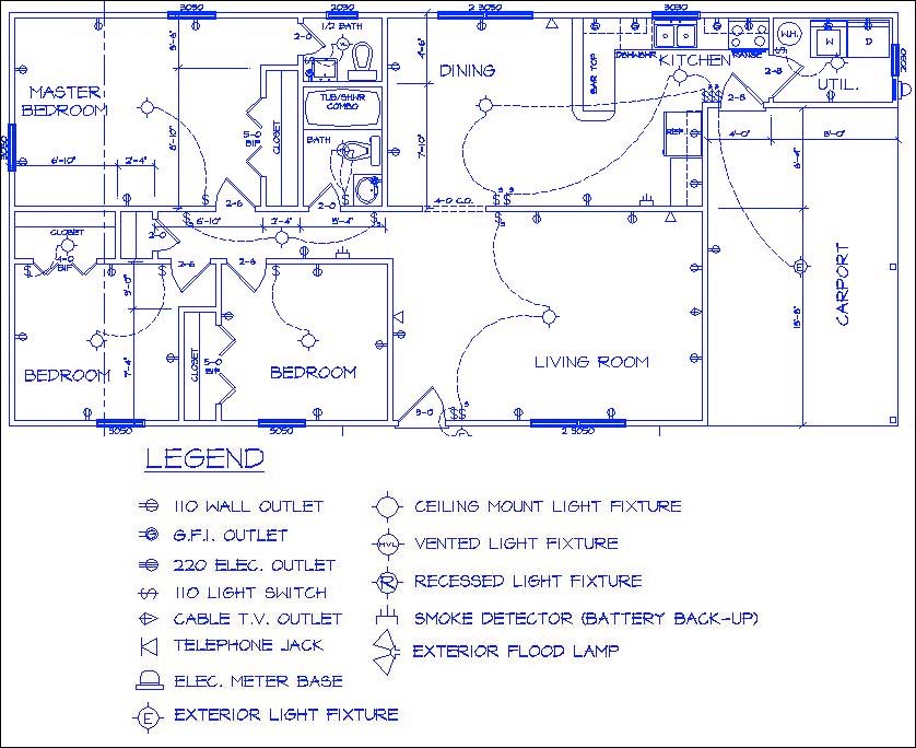
Placing outlets in a room. In general, outlets in a typical room are placed 12 feet apart. See National Electric Code for details.
Water supply
Potable (rhymes with coat-uh-bull) water = safe to drink (treated; chlorinated)
Water is often a scarce resource; nevertheless, almost 3/4 of potable water in the US is used for irrigation and flushing toilets—where potable water is not generally required.
Graywater can be used (water recovered from bathroom sinks, for example), in theory, for flushing toilets; but is not permitted under some building codes.
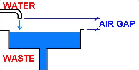
Sanitary drainage (waste)
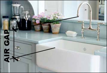
Air gap: Required between water and waste to prevent the waste from back-flowing into the potable water. Vacuum devices can sometimes be used where an air gap is not possible.
Water.
Water was traditionally placed in pipes that used gravity to reach all locations in buildings. Where buildings are too high, pumps are used (filling tanks at the top of the building (downfeed), which then use gravity—or pumping from storage tanks at the bottom of the building (upfeed).
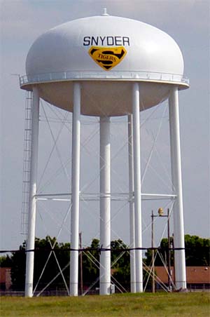
Water can also be pumped into water towers, which then feed communities using gravity.
Modern filtration systems require pressure (pumps) to force water through hi-tech filters, even when gravity would otherwise be sufficient.
TheSee this classic article by Pulitzer Prize-winning humorist Dave Barry.
Domestic hot water (versus water heated for hydronic heating systems). US = central hot water heaters in tanks; rest of world = tankless heaters where used.

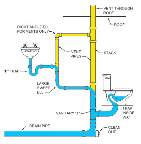
Sanitary drainage.
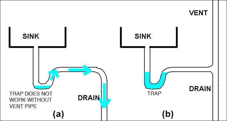
Water-borne (sanitary) waste from toilets, sinks, showers, etc. is piped to sewage treatment plants or septic fields, almost always using gravity (i.e., from high points to low points, e.g., to lakes and rivers). Sounds simple, but there is a big problem that needs to be overcome.
To put it bluntly, that shit stinks: listen to official Outkast sanitary drainage theme song.
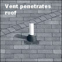
To prevent sewer gases from entering buildings through open drains, some sort of "trap" is needed.
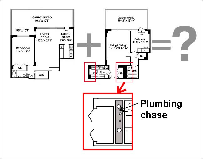
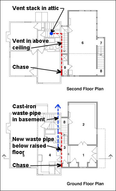
In buildings, water pipes are generally small and can often be threaded through walls. Waste pipes are often larger; 3 or 4 in. pipes may be inserted in stud or CMU walls, but often a plumbing chase is created—two walls with the pipes between them.
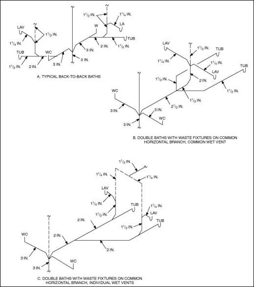
Plumbing schematic diagrams are often drawn as isometrics, showing fixtures, drains, and vents, along with required minimum sizes for all the pipes. Examples of acceptable configurations can be found in the 2000 IRC:
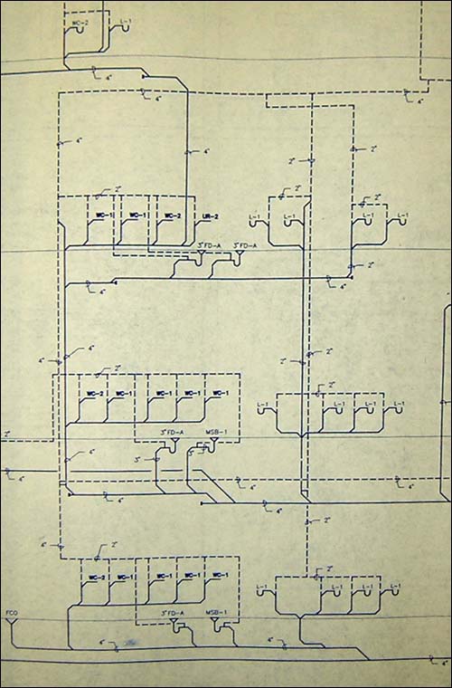
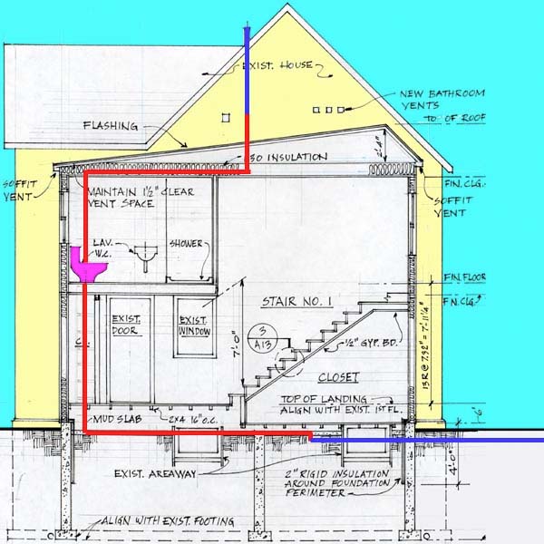
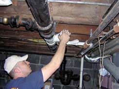
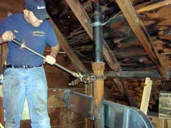
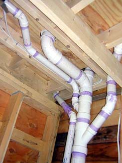
And here is my own adventure with plumbing: figuring out how to connect new fixtures in an addition to my home to the existing cast-iron waste line in the basement, and to the existing cast-iron vent in the attic.
Disclaimer: Students are responsible for material presented in class, and required material described on course outline. These notes are provided as a tentative outline of material intended to be presented in lectures only; they may not cover all material, and they may contain information not actually presented. Notes may be updated each year, and may or may not apply to non-current versions of course. first posted Nov. 20, 2012 | last updated: Dec. 8, 2020 Copyright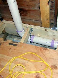