Jonathan Ochshorn
Sealant joints allow movement, but also supply continuity where materials are not only joined but need to connect in a continuous manner. Three main types:
low-range (caulks) with 5% movement capability, for minor cracks
medium-range (acrylics, butyl rubber) with 5-10% movement capability, e.g., for cladding joints that are non-movement joints
high-range (silicones, polyurethanes, polysulfides) with 25-100% movement capability, durable for up to 20 years, used for movements joints in cladding.
In other words, not all joints are equal: some come about because buildings are assembled from pieces, but have no associated movement (or very little). At one extreme, for pieces bearing on each other in compression (like traditional masonry construction), the space between these pieces can be filled with mortar that hardens into a firm and brittle — i.e., non-flexible — mass. At the other extreme, where movement between pieces is variable — i.e., might place the joint into tension — a brittle mortar-like fill would not work, and a more flexible (and "stretchable") substance is required.
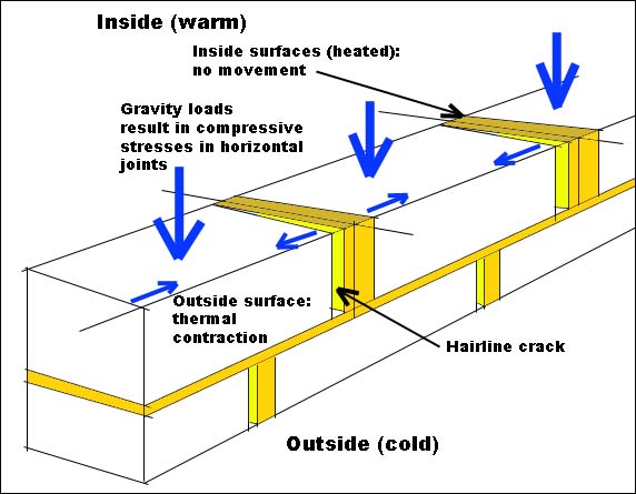
This difference in the behavior of joints subjected to compression only versus compression and tension (or tension only) explains in part why traditional masonry construction could be built without any control or expansion joints:
All horizontal joints are stressed almost exclusively in compression.
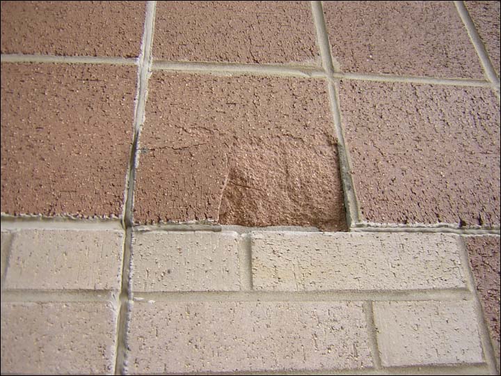
Because the bond between traditional mortar (lime-based) and the masonry units being joined is relatively weak, especially compared to modern mortar mixes, tension cracks at vertical joints (e.g., due to thermal contraction in cold weather) do not split the masonry units but instead create hairline cracks between the masonry units and the mortar.
Individual masonry units are relatively small, so that any thermal or shrinkage stresses which would place vertical joints into tension result in extremely small cracks — using larger units would result in larger movement-induced cracks.
Movement capability is defined as the amount of movement that the sealant is capable of, divided by its original width, and expressed as a percentage. Note that 100% movement capability in a sealant refers to its ability to expand only; such a sealant might have a 50% movement capability when it contracts. This is because nothing can contract 100% — that would be like having a 1 inch joint width that contracted to 0 inches.
Letting:
Examples of movement capability:
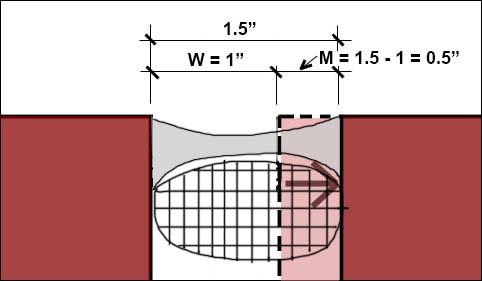
If a sealant fills a 1 inch gap and can expand to a total gap width of 1.5 inches, then its movement capability (for expansion) = (0.5 / 1.0) x 100 = MC = 50%. Note that the actual expansion, M, is not 1.5 inches, but rather 1.5 - 1 = 0.5 inches.
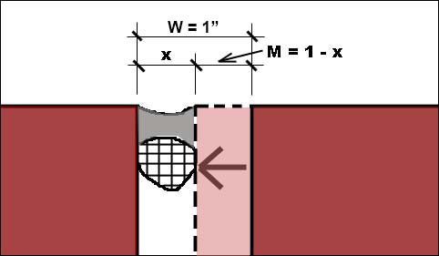
If the same sealant (filling a 1 inch gap with a MC = 50%) contracts, the gap, x, corresponding to the smallest contraction would be (1 - x / 1.0) x 100 = 50; or x = 0.5 in. or 1/2 in. Here, the expression "1 - x" corresponds to the actual contraction, M. In other words, since it can contract 1/2 in. and its original width is 1 in., the movement capability in compression is (0.5 / 1.0) x 100 = 50%.
If the anticipated movement in a joint is 0.3 in., and the sealant used has a movement capability of 100% (in tension), how wide must the joint be to accommodate the anticipated movement? To find the necessary joint width, W, we write: (0.3 / W) x 100 = 100; or W = 0.3 inches. In other words, the original width of 0.3 inches doubles to become 0.6 inches, which allows for the anticipated 0.3 inches of movement. If the original width were smaller, say 0.2 inches, then the maximum expansion with 100% movement capability would be 0.2 inches, which is less than the anticipated movement.
If the anticipated movement in a joint is 0.3 in., and the sealant used has a movement capability of 75% (in tension), what is the required width, W, of the joint to accommodate the anticipated movement? (0.3 / W) x 100 = 75; or W = 0.4 inches. In other words, the original width of 0.4 inches gets multiplied by 1.75 to become 0.7 inches, which allows for the anticipated 0.3 inches of movement.
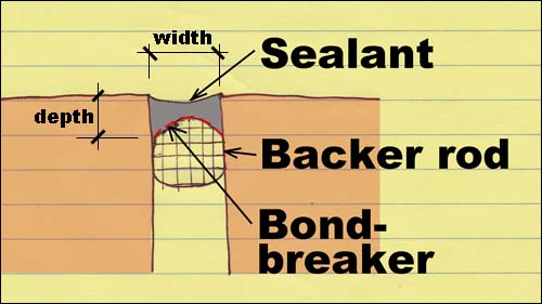
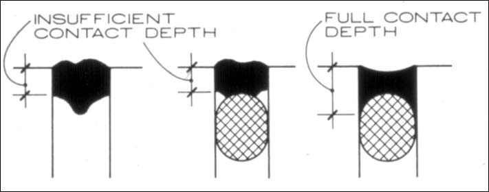
Sealant joints typically consist of the sealant itself, and a backer (back-up) rod; the rod has a "bond breaker" to prevent adhesion of the sealant to the rod. The bond breaker is either applied as a separate element (like a piece of slippery tape) or is integral with the backer rod.
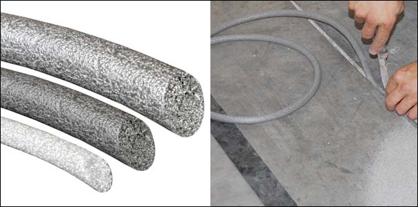
The backer rod has three primary functions:
It creates a back surface so that the sealant is only applied where it is needed.
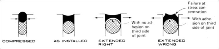
It defines the shape of the sealant so that it can properly expand and contract within the joint.
It provides a surface for a bond breaker (often integral with the backer rod itself) to prevent adhesion of the sealant to the back surface. This is important so that the sealant can expand and contract properly.
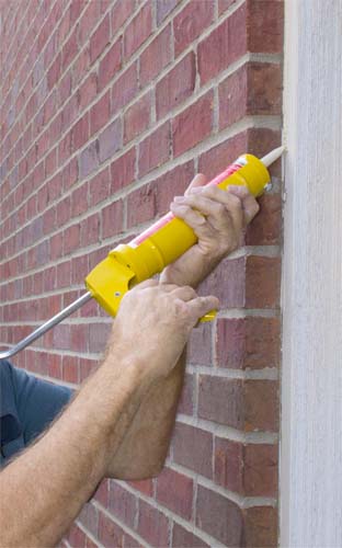
Sealant installation video
Sealant installation video (Milstein Hall, Cornell)
Typical joints range in width from 1/4" to 1-2". The depth of the sealant joint is 1/2 of the width, except that it is limited to a minimum of 1/4" and a maximum of 1/2" (these two values are sometimes given as 1/8" and 3/8" respectively).
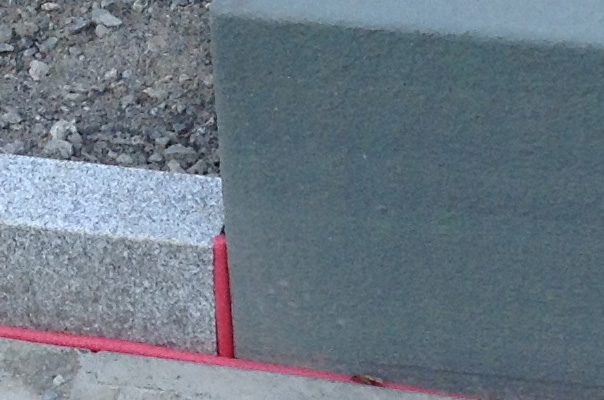
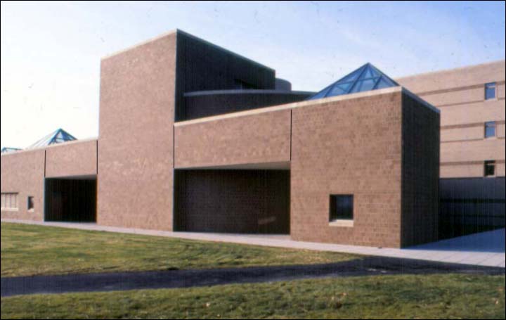
The image below (Kennedy-Roberts hall, Cornell, Gwathmey-Siegel Architects) shows the location of sealant joints in the brick veneer. Typically, the joints correspond to (1) shelf angles at the floor levels and (2) column lines, resulting in a pattern of rectangular "panels" of brick, each of which can move separately.

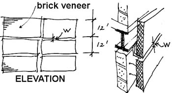
Find the necessary joint width, W, for the horizontal sealant joint shown above.
Assume the following:
The solution is best found by constructing a table with columns for maximum joint contraction (i.e., brick expansion), and maximum joint expansion (brick contraction). Note that 144" refers to the panel height, i.e., 12 feet. You can also use my online sealant joint width calculator to arrive at the same results.
| Max. joint contraction | Max. joint expansion | |
| thermal expansion | (144")(0.0000036)(90-45) = 0.023" | (144")(0.0000036)(65-0) = 0.034" |
| moisture expansion | (144")(0.0005) = 0.072" | (144")(0) = 0" |
| structural deflection | 0.125" | 0.125" |
| subtotal: all joint movement | 0.220" | 0.159" |
| required sealant width multiplier for movement: 100 / MC = 100/25 = 4 |
4 x 0.220" = 0.880 | 4 x 0.159" = 0.636 |
| additional sealant width for tolerance | 0.1875" | 0.1875" |
| Total sealant joint width | 0.880 + 0.1875 = 1.068" | 0.636 + 0.1875 = 0.824" |
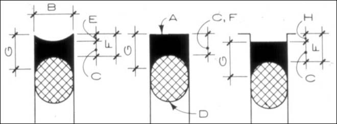
The answer is 1.068" or, rounding to the nearest 1/8" increment, approximately 1-1/8". A section through that horizontal joint is shown in the sketch below:
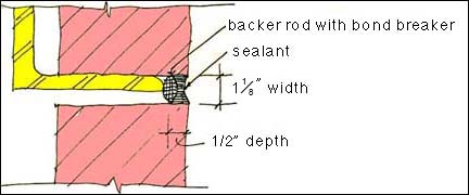
Of course, the sealant joint width would be a bit less if the moisture expansion of the brick was taken as 0.0002 or 0.0003. This judgment can be made based, in part, on the amount of time that the brick has been out of the kiln.
* Coefficients of thermal expansion: Scroll down to bottom of page for table of common values. For the example used here: 3.6 x 10-6 = 0.0000036.
** Moisture expansion in brick: "Based on past research, long term moisture expansion of brick can be estimated at between 0.0002 and 0.0009. A design value of 0.0003 should be used when designing composite masonry walls. A design value of 0.0005 should be used in veneer walls where an upper bound of movement is estimated."
Links to technical notes on brick construction can be found here.
| Material | in. per in. per degree F x 10-6 |
|---|---|
Masonry
|
3.6 - 4.0 5.2 4.3 |
Concrete
|
5.5 4.3 |
Plaster
|
6.6 9.2 |
Stone
|
4.4 2.8 3.7 - 7.3 |
Metal
|
13.2 10.4 10.1 5.9 9.4 15.9 9.6 6.7 |
Wood, parallel to grain
|
2.1 3.0 2.7 |
Wood, perpendicular to grain
|
32 19 30 |
| Glass | 5.0 |

Disclaimer: Students are responsible for material presented in class, and required material described on course outline. These notes are provided as a tentative outline of material intended to be presented in lectures only; they may not cover all material, and they may contain information not actually presented. Notes may be updated each year, and may or may not apply to non-current versions of course.
first posted Nov. 5, 2012 | last updated: October 28, 2020
Copyright
2007–2020 J. Ochshorn. All rights reserved. Republishing material on this web site, whether in print or on another web site, in whole or in part, is not permitted without advance permission of the author.