ARCH 2615-5615 Building Technology II: Structural Elements
Spring 2022
Jonathan Ochshorn
Assignment 4 solutions
Refer to Assignment 4 for loads and other parameters, as reproduced below.
For the framing plans and sections that you created for Assignment 3, assume the following:
Office occupancy with L = 50 psf. Consider live load reduction to determine the reduced live load.
Dead load (for floors and roof) = 55 psf.
Snow load = 35 psf.
Construction/maintenance roof live load, Lr = 30 psf.
Use A-992 steel wide-flange sections for all beams, girders, and columns.
Design beams and girders with an allowable live load deflection of L/360 and an allowable total load deflection of L/240.
Choose any interior beam, girder, and column from your Assignment 3 proposal.
Requirements
A. Using the online calculators for column governing loads, steel beams, and steel columns, design the following elements:
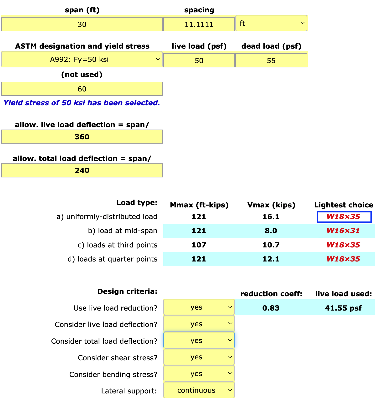
- Typical beam:
Select a W18x35 (see screen shot below)
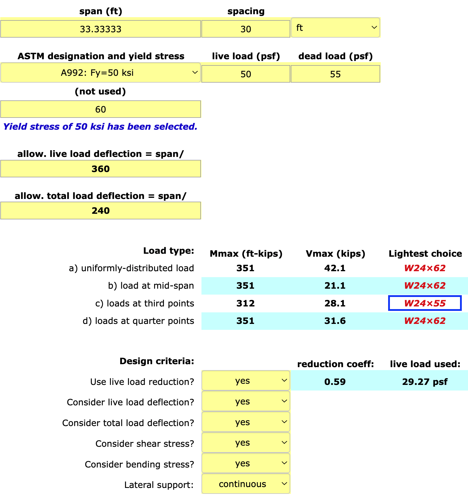
- Typical girder:
Select a W24x55 (see screen shot below)
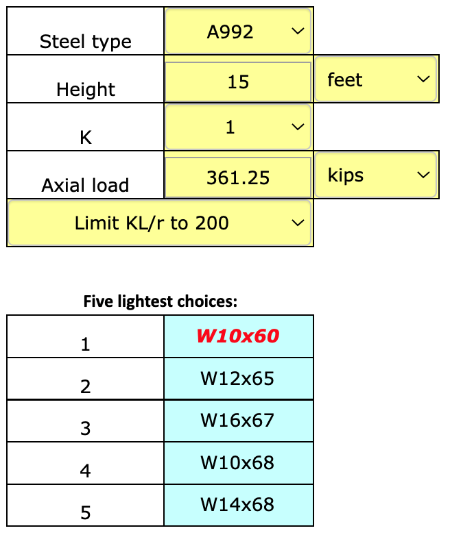
- First-floor interior column (assume 15-foot height).
First, find the governing load of 361.25 kips, as shown below.
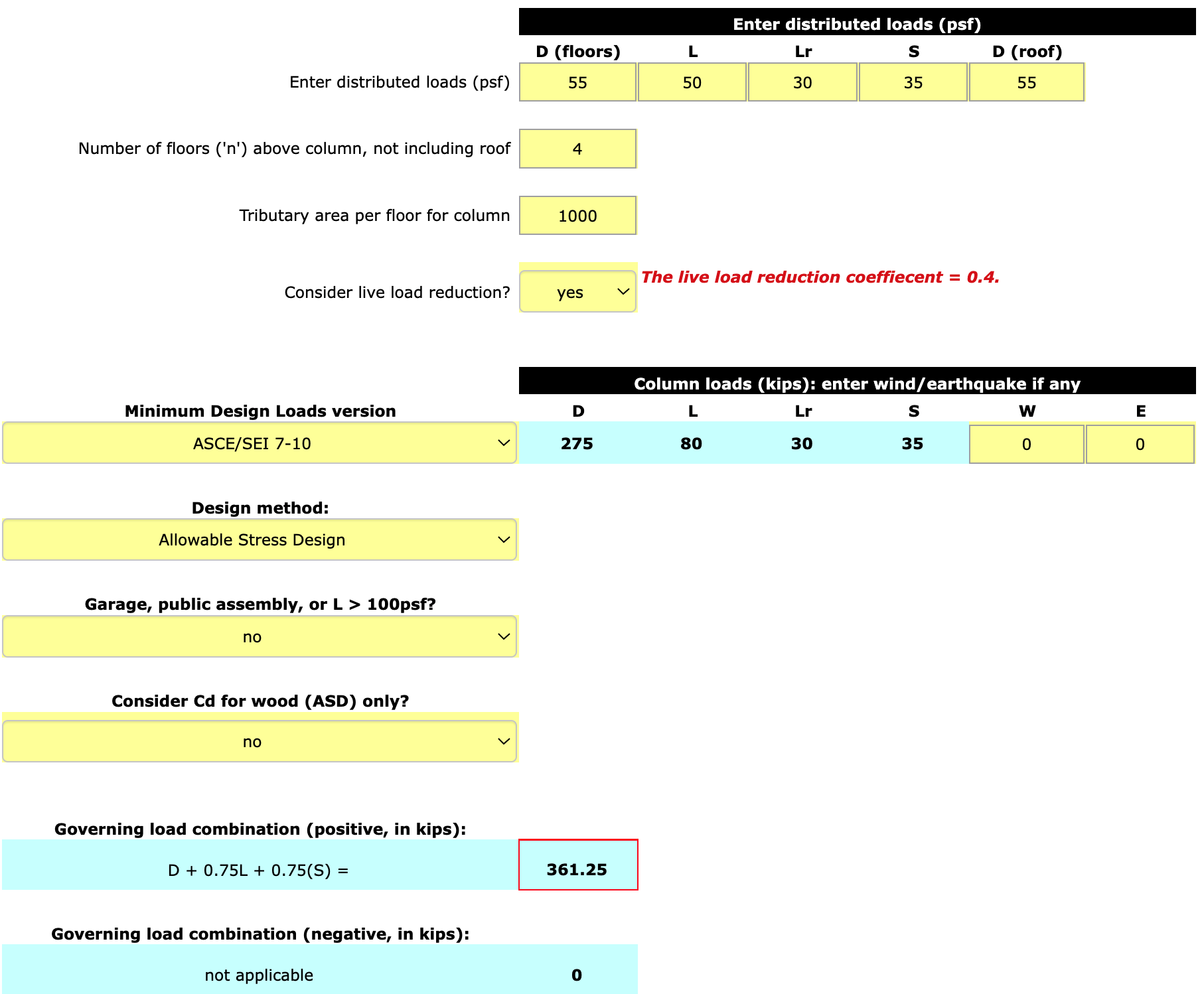
Next, use the governing load found above (361.25 kips) to select a wide-flange steel column with an unbraced length of 15 feet, as shown below.
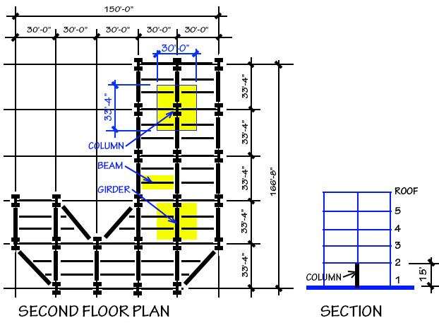
Include framing plans from your assignment 3 project showing the spans and spacing of the selected beam and girder, as well as the tributary area dimensions for your selected interior first-floor column (you may assume that the tributary area for your interior column is the same on all floor/roof levels).
Include screen shots of the relevant calculators (with the correct answer circled) in your pdf.
B. Design the typical steel wide-flange beam without using the calculators. You may not get the same answer as you did using the calculator, since we'll stop if the deflection calculations show that the beam is no good. In any case, show all your calculations, step by step! You can refer to your class notes (pdf) or to Example 4.6 in the text.
First, we find the reduced live load, since this was a criterion in the assignment. The beam tributary area, At = 30 × 11.111 = 333.333, so the reduction coefficient is 0.25 + 15 / sq.rt.(333.333 × 2) = 0.83, and therefore the reduced live load = 50(0.83) = 41.5 psf.
Next, we draw load, shear, and moment diagrams:
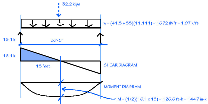
Next, we find the required plastic section modulus, Zreq = Mmax / (0.6Fy), where Mmax = 1447 in-k (see moment diagram above) and Fy = 50 ksi (see Appendix Table A-4.1). Therefore:
Zreq = 1447 / (0.6×50) = 48.2 in3.
We find the provisional cross section from Appendix Table A-4.15:
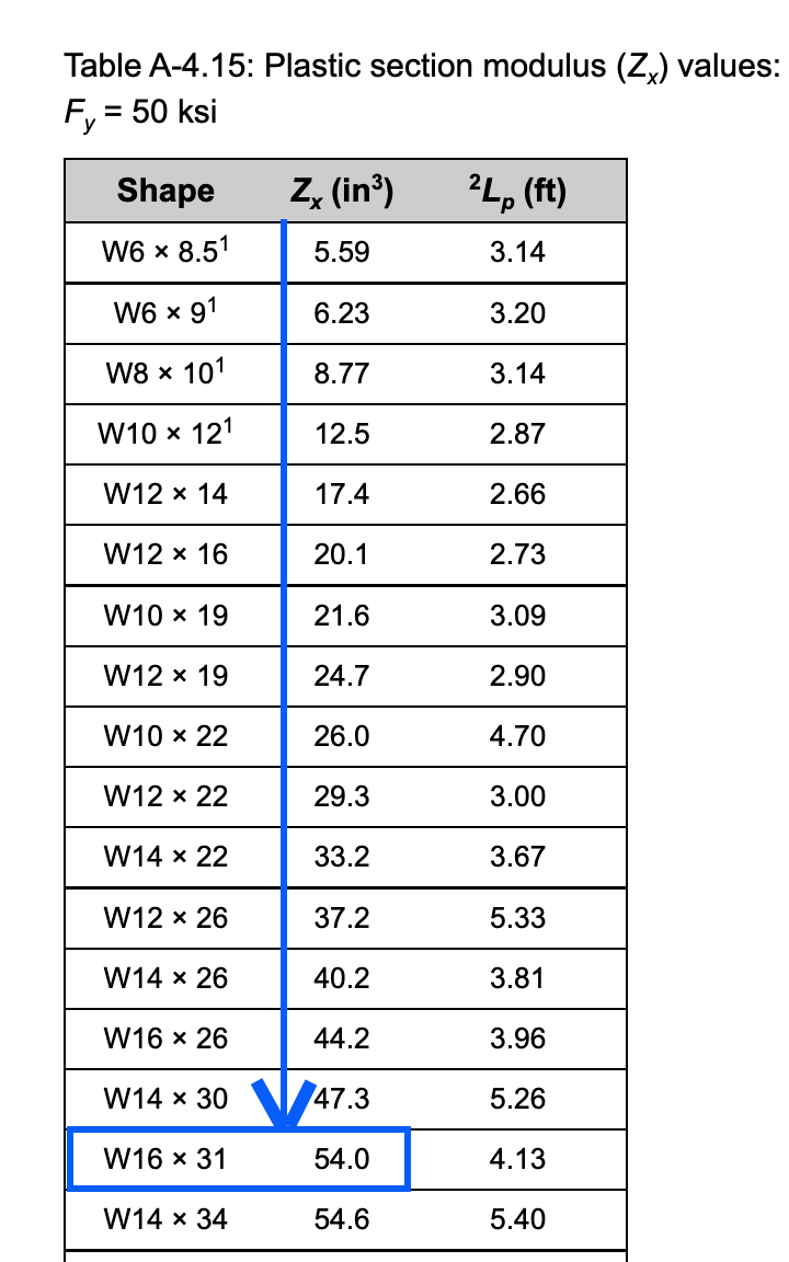
The provisional selection is a W16x31.
Now, check the provisional section for shear: First, find the web dimensions in Appendix Table A-4.3: d = 15.9 in. and the web thickness, tw = 0.275 in. The actual web area = (15.9)(0.275) = 4.3725 in2.
The required web area = V / (0.4 Fy) = 16.1 / (0.4x50) = 0.805 in2 which is less than the required web area, so the beam is OK for shear. Note that 0.4 Fy is used unless the W-section has the footnote "3," in which case the coefficient used is 0.36 Fy.
We now check for deflection. For total load deflection, the allowable deflection = span/240 = 30x12/240 = 1.5 in. We multiply the span (30 feet) by 12 to convert the span to inch units.
We use Appendix Table A-4.17 to compute the actual total load deflection = CP(L/12)3 / (EI), where the coefficient, C = 22.46 for a simply-supported beam carrying a uniformly-distributed load; and the total load resultant, P = 32.2 kips (see load diagram above). Note that the modulus of elasticity for steel is always taken as 29,000 ksi (see Note 1 in Appendix Table A-4.1) and the moment of inertia for the provisional section, Ix = 375 in4, found in Appendix Table A-4.3. Therefore:
Δactual = 22.46(32.2)(303) / (29,000 x 375) = 1.8 in.
Because the actual total-load deflection is greater than the allowable total-load deflection, the provisional beam is no good, and we can stop! In an actual design process, we would select a larger cross section (as the calculator has done) so that it would satisfy the deflection criteria.
We really don't need to check live load deflection in this case, since the beam is already "no good" for total-load deflection, but — just for the record — the calculations are as follows:
For live load deflection, the allowable deflection = span/360 = 30x12/360 = 1.0 in.
We use Appendix Table A-4.17 to compute the actual live load deflection = CP(L/12)3 / (EI), where the coefficient, C = 22.46 for a simply-supported beam carrying a uniformly-distributed load; and the live load resultant, P = 41.5 x 11.111 x 30 /1000 = 13.85 kips. Note that the modulus of elasticity and the moment of inertia remain the same as for total-load deflection. Therefore:
Δactual = 22.46(13.85)(303) / (29,000 x 375) = 0.77 in.
Because the actual live-load deflection is less than the allowable live-load deflection, the provisional cross section is OK for live-load deflection, as it turns out.
Copyright
2021 J. Ochshorn. All rights reserved. First posted: 17 March 2022 | last updated: 17 March 2022
ARCH 2615-5615 Building Technology II: Structural Elements
Spring 2022
Jonathan Ochshorn
Assignment 4 solutions
Refer to Assignment 4 for loads and other parameters, as reproduced below.
For the framing plans and sections that you created for Assignment 3, assume the following:
Office occupancy with L = 50 psf. Consider live load reduction to determine the reduced live load.
Dead load (for floors and roof) = 55 psf.
Snow load = 35 psf.
Construction/maintenance roof live load, Lr = 30 psf.
Use A-992 steel wide-flange sections for all beams, girders, and columns.
Design beams and girders with an allowable live load deflection of L/360 and an allowable total load deflection of L/240.
Choose any interior beam, girder, and column from your Assignment 3 proposal.
Requirements
A. Using the online calculators for column governing loads, steel beams, and steel columns, design the following elements:
Select a W18x35 (see screen shot below)
Select a W24x55 (see screen shot below)
First, find the governing load of 361.25 kips, as shown below.
Next, use the governing load found above (361.25 kips) to select a wide-flange steel column with an unbraced length of 15 feet, as shown below.
Include framing plans from your assignment 3 project showing the spans and spacing of the selected beam and girder, as well as the tributary area dimensions for your selected interior first-floor column (you may assume that the tributary area for your interior column is the same on all floor/roof levels).
Include screen shots of the relevant calculators (with the correct answer circled) in your pdf.
B. Design the typical steel wide-flange beam without using the calculators. You may not get the same answer as you did using the calculator, since we'll stop if the deflection calculations show that the beam is no good. In any case, show all your calculations, step by step! You can refer to your class notes (pdf) or to Example 4.6 in the text.
First, we find the reduced live load, since this was a criterion in the assignment. The beam tributary area, At = 30 × 11.111 = 333.333, so the reduction coefficient is 0.25 + 15 / sq.rt.(333.333 × 2) = 0.83, and therefore the reduced live load = 50(0.83) = 41.5 psf.
Next, we draw load, shear, and moment diagrams:

Next, we find the required plastic section modulus, Zreq = Mmax / (0.6Fy), where Mmax = 1447 in-k (see moment diagram above) and Fy = 50 ksi (see Appendix Table A-4.1). Therefore:
Zreq = 1447 / (0.6×50) = 48.2 in3.
We find the provisional cross section from Appendix Table A-4.15:

The provisional selection is a W16x31.
Now, check the provisional section for shear: First, find the web dimensions in Appendix Table A-4.3: d = 15.9 in. and the web thickness, tw = 0.275 in. The actual web area = (15.9)(0.275) = 4.3725 in2. The required web area = V / (0.4 Fy) = 16.1 / (0.4x50) = 0.805 in2 which is less than the required web area, so the beam is OK for shear. Note that 0.4 Fy is used unless the W-section has the footnote "3," in which case the coefficient used is 0.36 Fy.
We now check for deflection. For total load deflection, the allowable deflection = span/240 = 30x12/240 = 1.5 in. We multiply the span (30 feet) by 12 to convert the span to inch units.
We use Appendix Table A-4.17 to compute the actual total load deflection = CP(L/12)3 / (EI), where the coefficient, C = 22.46 for a simply-supported beam carrying a uniformly-distributed load; and the total load resultant, P = 32.2 kips (see load diagram above). Note that the modulus of elasticity for steel is always taken as 29,000 ksi (see Note 1 in Appendix Table A-4.1) and the moment of inertia for the provisional section, Ix = 375 in4, found in Appendix Table A-4.3. Therefore:
Δactual = 22.46(32.2)(303) / (29,000 x 375) = 1.8 in.
Because the actual total-load deflection is greater than the allowable total-load deflection, the provisional beam is no good, and we can stop! In an actual design process, we would select a larger cross section (as the calculator has done) so that it would satisfy the deflection criteria.
We really don't need to check live load deflection in this case, since the beam is already "no good" for total-load deflection, but — just for the record — the calculations are as follows:
For live load deflection, the allowable deflection = span/360 = 30x12/360 = 1.0 in.
We use Appendix Table A-4.17 to compute the actual live load deflection = CP(L/12)3 / (EI), where the coefficient, C = 22.46 for a simply-supported beam carrying a uniformly-distributed load; and the live load resultant, P = 41.5 x 11.111 x 30 /1000 = 13.85 kips. Note that the modulus of elasticity and the moment of inertia remain the same as for total-load deflection. Therefore:
Δactual = 22.46(13.85)(303) / (29,000 x 375) = 0.77 in.
Because the actual live-load deflection is less than the allowable live-load deflection, the provisional cross section is OK for live-load deflection, as it turns out.
Copyright
2021 J. Ochshorn. All rights reserved. First posted: 17 March 2022 | last updated: 17 March 2022