contact | contents | bibliography | illustration credits | ⇦ chapter 9 |
10. RAINWATER CONTROL

The probability of water leaking through joints increases when "critical" seals—those designed to exclude water—are detailed and constructed using only sealants, as is the case with many joints in Milstein Hall. The causes of sealant failure are too numerous to outline here. Karen Warseck suggests that while such failure is usually due to "a combination of factors," the underlying reason is "a lack of attention to detail. Too often, since the sealants are a small percentage of the work, they are perfunctorily specified, easily substituted, and haphazardly applied. Yet successful joints require meticulous design, precise sealant selection, and painstaking application."1 Numerous instances of leaks, including some which seem to be sealant joint failures, have already arisen in Milstein Hall, through both roofs and curtain walls.
Water leaking through walls
The first leaks in Milstein Hall occurred in the below-grade level. Shortly before construction was completed in 2011, water appeared in the corridor adjacent to the lower-level gallery (fig. 10.1). At the same time, leaks appeared at the edge of a stair leading to a different hallway to Sibley Hall (fig. 10.2 top left) and four years later, in 2015, leaks continued at the same place (fig. 10.2 bottom left).
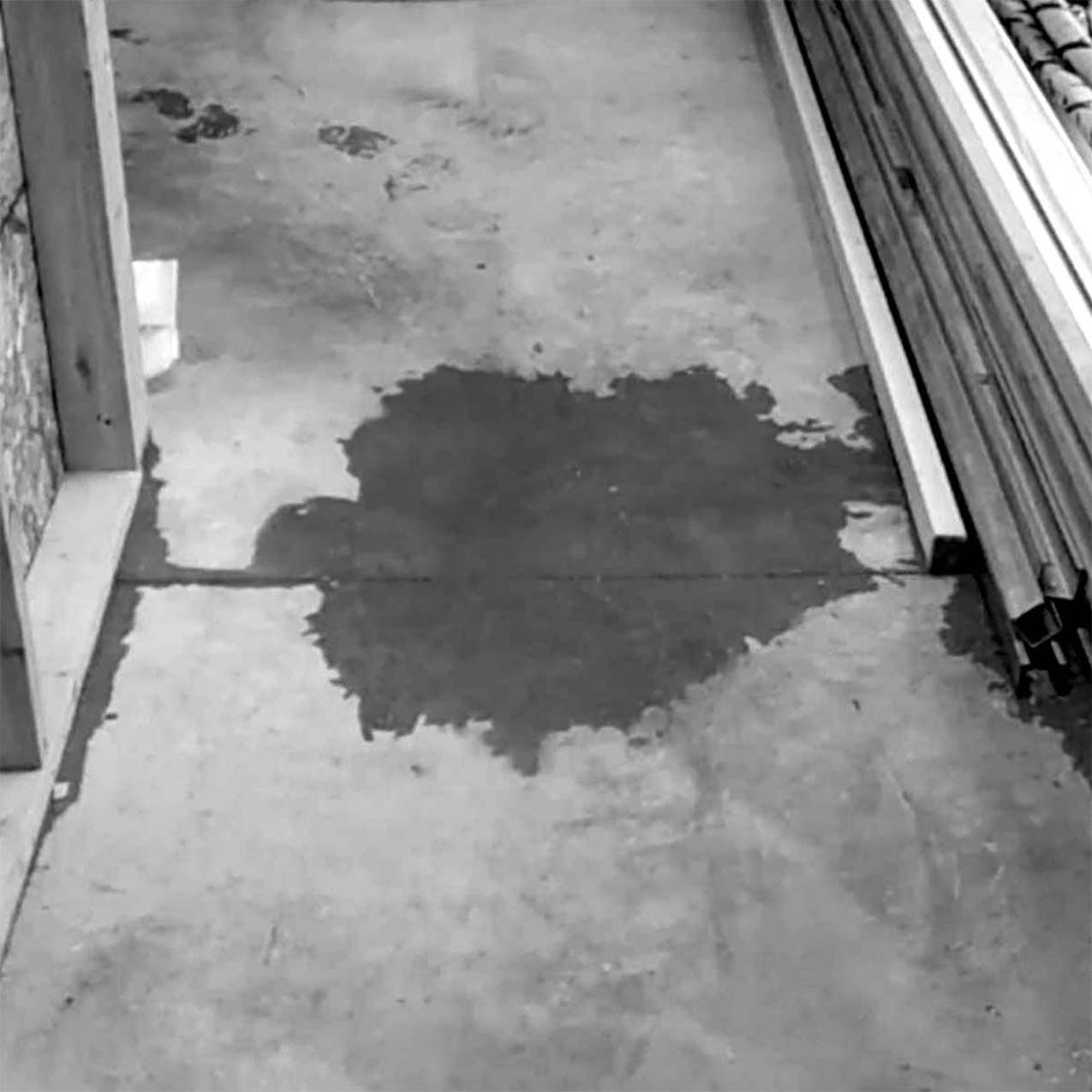
Figure 10.1. Water was leaking into the lower level of Milstein Hall in September 2011, just before it was occupied, in a corridor next to the gallery.
In a sense, this leak is not surprising—it occurs at the intersection of Milstein Hall and Sibley Hall, two buildings with extremely different enclosure systems. East Sibley Hall was completed in 1894 and its rear wall is solid brick over a stone foundation that was covered, according to the Milstein Hall demolition drawings, with a "concrete shelf … to hide old foundation demolition" (fig. 10.2 right). Milstein Hall, on the other hand, is a modern building with a storefront-type curtain wall system on an insulated concrete foundation protected with a waterproofing membrane.
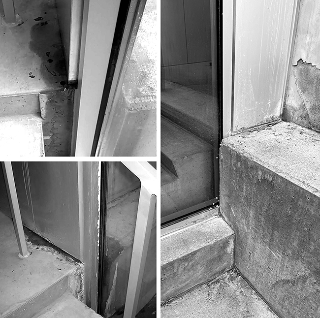
Figure 10.2. The joint between Milstein Hall's stair landing at the basement level, leading into Sibley Hall, leaked initially in September 2011 (top left), just before the building was occupied. It leaked again in March 2015 (bottom left) at the same location. The complexity of this condition (right) is evident in this exterior view, from May 2023: Milstein Hall's concrete stair and landing can be seen through the glazed curtain wall; the landing aligns with a concrete ledge ("seat") covering the foundation of Sibley Hall.
The two systems simply do not join together very well, since the control layers in Milstein Hall (i.e., the various membranes and insulation for water, air, vapor, and thermal control) have no appropriate analogues in Sibley Hall, which is a mass reservoir wall consisting of solid brick. A rainwater control layer in Milstein Hall, for example, cannot be attached to a rainwater control layer in Sibley Hall where the two buildings come together, because Sibley Hall has no rainwater control layer. Like all traditional mass-reservoir-type building enclosures, Sibley Hall's brick wall is designed to absorb rainwater, which eventually evaporates to the exterior or interior. Therefore, Milstein Hall's rainwater control layer (its waterproofing membrane) must somehow be flashed deep enough into Sibley Hall's brick wall so that rainwater, penetrating above the flashing into Sibley Hall's brick wall, cannot bypass the flashing and return, below the flashing, into Milstein Hall. Yet many flashing details at the intersection of Milstein and Sibley Halls, for example at the seismic joint illustrated schematically in fig. 9.6, consist only of reglets (grooves within the mortar joints) that barely penetrate into the brick. And reglets simply do not work in this context.2
The general question of flashing where Milstein and Sibley Halls come together is made even more difficult because the geometry of the two buildings at the location of the leak is actually quite complex, with a concrete ledge ("shelf " or "seat") at the foundation of Sibley Hall aligning with the upper landing of a concrete stair in Milstein Hall. An insulated wall with a metal finish on both sides separates them at the upper landing, while a curtain wall system butts up against this metal-clad wall beyond the landing—these two wall systems are "connected" with nothing more than sealant joints. Sealant joints are also used at the intersection of the new metal partition with the existing masonry wall of Sibley Hall and with the new concrete ledge covering Sibley Hall's old masonry foundation (fig. 10.3). Relying on sealant joints for rainwater control where modern control layers intersect traditional masonry or concrete walls, ledges, or decks is even worse than relying on reglets, since not only can water work its way through cracks in masonry or concrete surfaces as with reglets, but the sealant joints themselves—as noted above—are notoriously difficult to execute properly.
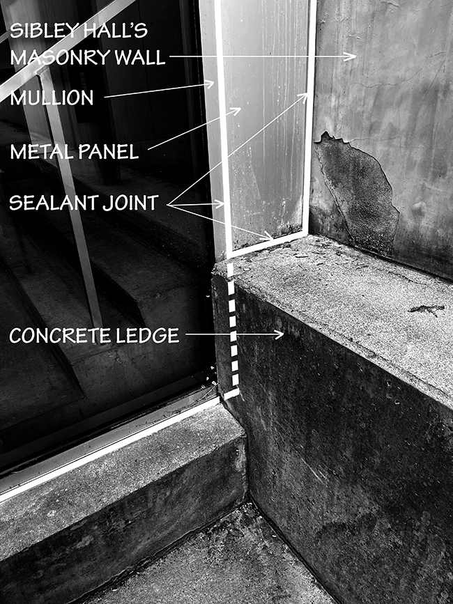
Figure 10.3. Intersection of Milstein and Sibley Halls at basement stair landing, May 2023: trying to create a water control layer by relying on sealant joints, especially at the intersection of concrete or masonry surfaces, is likely to fail.
Water leaking through basement roofs: efflorescence
In addition to leaking of rainwater through the building enclosure, water leaks can manifest themselves in other ways, especially when water is conducted in or through certain mortar, masonry, or concrete materials. This seems to be the case at the lower level of Milstein Hall, where white powdery material has appeared in the ceiling itself, and especially on the aluminum "storefront" mullions at the west end of Milstein Hall (fig. 10.4).
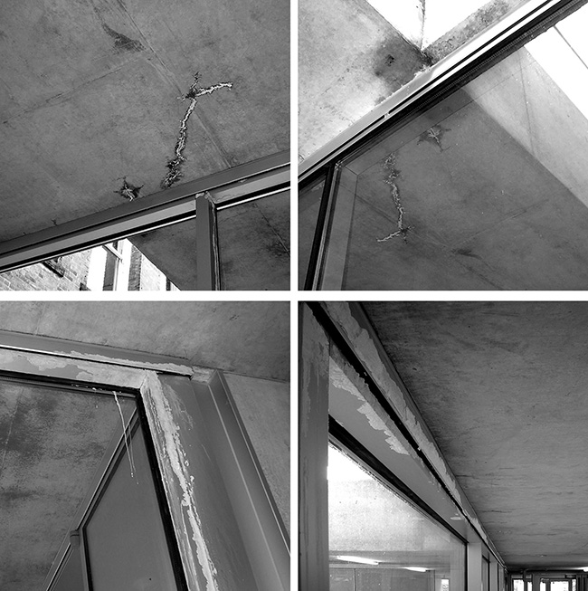
Figure 10.4. Efflorescence in Milstein Hall (July 2013) has occurred where water enters the concrete roof deck, e.g., above the gallery near the loading area, and migrates to interior surfaces, carrying soluble salts.
This is an example of efflorescence, a phenomenon in which soluble salt deposits are left behind on the concrete surface as water evaporates after leaking through the concrete slab. There is some question about the origin of these salt deposits: "The essential process involves the dissolving of an internally held salt in water… The water, with the salt now held in solution, migrates to the surface, then evaporates, leaving a coating of the salt. In what has been described as 'primary efflorescence,' the water is the invader and the salt was already present internally, and a reverse process, where the salt is originally present externally and is then carried inside in solution, is referred to as 'secondary efflorescence.' "3
In fact, researchers have discovered that it is not the movement of excess water in the concrete, but rather it is calcium hydroxide, formed as cement cures, that does the moving. In other words, the calcium hydroxide "diffuses up through the water-filled capillary system of the concrete to the surface" where it reacts with CO2 in the air to form calcium carbonate, the white powdery substance that is given the name efflorescence.4
It's not clear whether the salts in these instances of efflorescence come from snow-melting protocols (winter road salt) above the deck, or whether the salts were already in the concrete. In either case, water continues to migrate into the concrete deck from above, and works its way through the deck to various interior surfaces. It appears that the problem with efflorescence in Milstein Hall is different from the mostly benign "primary" efflorescence, a one-time phenomenon caused by excess water in the cement that ceases to be a problem after a few months, when the excess water evaporates. Rather, it may be the more problematic "secondary" type, and could well be exacerbated by the use of road salt in the winter. More than a decade after Milstein Hall's completion, instances of what appear to be secondary efflorescence can still be found (fig. 10.5).
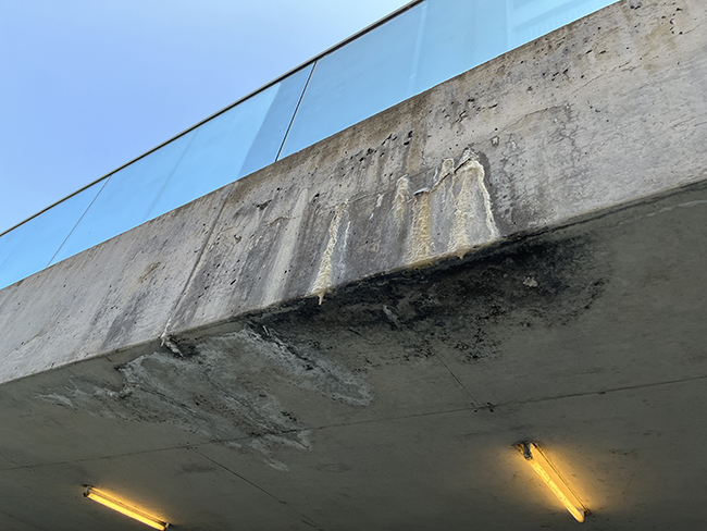
Figure 10.5. Efflorescence can still be seen on the soffit and fascia of the concrete deck supporting the loading area at Milstein Hall, more than a decade after its construction (image taken May 2023). Stalactites, possibly caused by dissolved cement stone, are an indication of a potential structural problem.
The potential problem with this type of efflorescence is that the absorbed salt "can begin to dissolve cement stone, which is of primary structural importance. Virtual stalactites can be formed in some cases as a result of dissolved cement stone, hanging off cracks in concrete structures. Where this process has taken hold, the structural integrity of a concrete element is at risk."5
The mechanism for water entry into the concrete deck above occupied basement spaces in Milstein Hall is discussed in the following section.
Water leaking through basement roofs: Bibliowicz Gallery
I was walking outside of Milstein Hall in the summer of 2012 when I noticed some construction activity in the Milstein Hall basement gallery. The entire storefront glazing system had been dismantled, with the aluminum frames and glazing panels stockpiled in the adjacent garden (fig. 10.6).
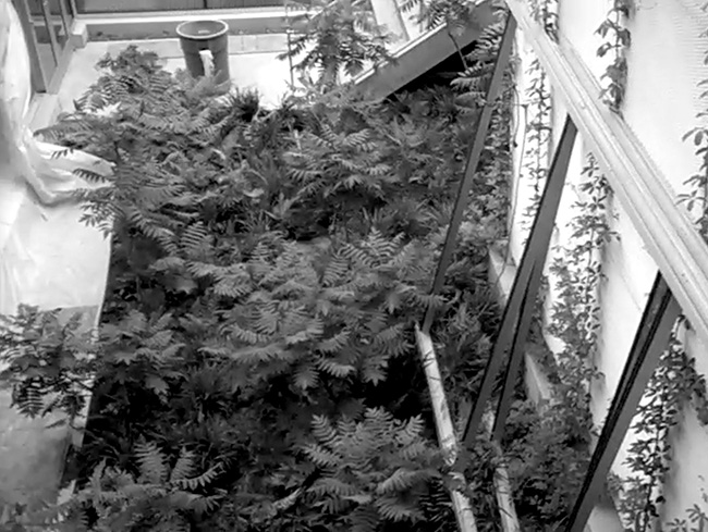
Figure 10.6. Windows and window frames were removed from the Bibliowicz Gallery in Milstein Hall during the summer 2012; aluminum window frames were temporarily stored against the exterior stair tower in the sunken garden; glazing panels were also stored in the garden.
Over the next few days, the mullions were put back in place, and the glass was re-inserted. It turns out that water had been leaking into the gallery space where the concrete ceiling meets the top of the aluminum frames for the glazing, possibly through cracks in the concrete deck over the gallery, as shown schematically in figure 10.7 (left). In this detail, as originally designed and built, water seems to have a clear pathway to the top of the aluminum mullion, where the waterproof membrane intended to direct such water through weep holes to the outside would have been difficult to implement in practice. And even if it had worked in that manner, directing water through the concrete deck and fascia would have resulted in efflorescence appearing on the exterior surfaces of the concrete, aluminum, and glass.
Water, once it penetrates into the concrete slab, can easily get through or around the rigid insulation, which is not designed as a waterproof layer. The repairs that I witnessed in the summer of 2012, a little more than one year after Milstein Hall was first occupied, involved removing the aluminum mullions and glass; cutting a kerf into the concrete ceiling of the gallery just inside the top horizontal mullion; inserting a bent metal plate, intended to function as a water stop, to prevent water from entering the gallery; and finally replacing the aluminum mullions and glazing (fig. 10.7 right).
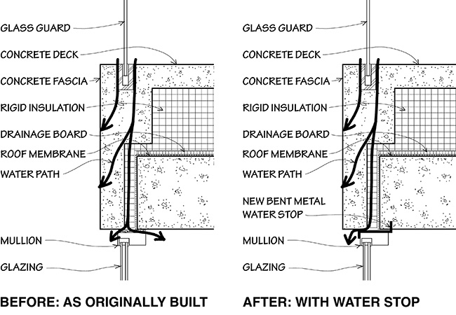
Figure 10.7. Water appears in the gallery in Milstein Hall and causes efflorescence to appear on the fascia and exterior glazing, presumably entering through cracks in the concrete deck, and working its way down to the top of the mullion (left); a bent metal water stop was inserted above the mullion, in 2012, to direct water reaching the mullion to the exterior (right). In these schematic sections, based on Milstein Hall working drawings, a second drainage board, that seems to have been installed above the insulation, is not shown.
After these repairs were completed, one could still see residual efflorescence and water stains in the gallery ceiling, adjacent to the new bent metal water stop at the top of the aluminum mullions (fig. 10.8).
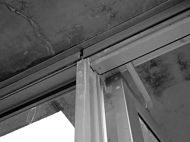
Figure 10.8. Water stains and efflorescence are still visible after a bent metal water stop was inserted into a kerf cut into the concrete ceiling of the Bibliowicz Gallery at Milstein Hall in 2012.
In addition, as I remarked at the end of a short Milstein Hall video, part of my online critique of Milstein Hall uploaded in 2013, "it is likely that water will still be an issue, as the underlying problem was not fixed."6 Water was still entering through cracks in the concrete deck and causing efflorescence to appear on the concrete fascia and soffit, as well as on the exterior glazing (fig. 10.9).
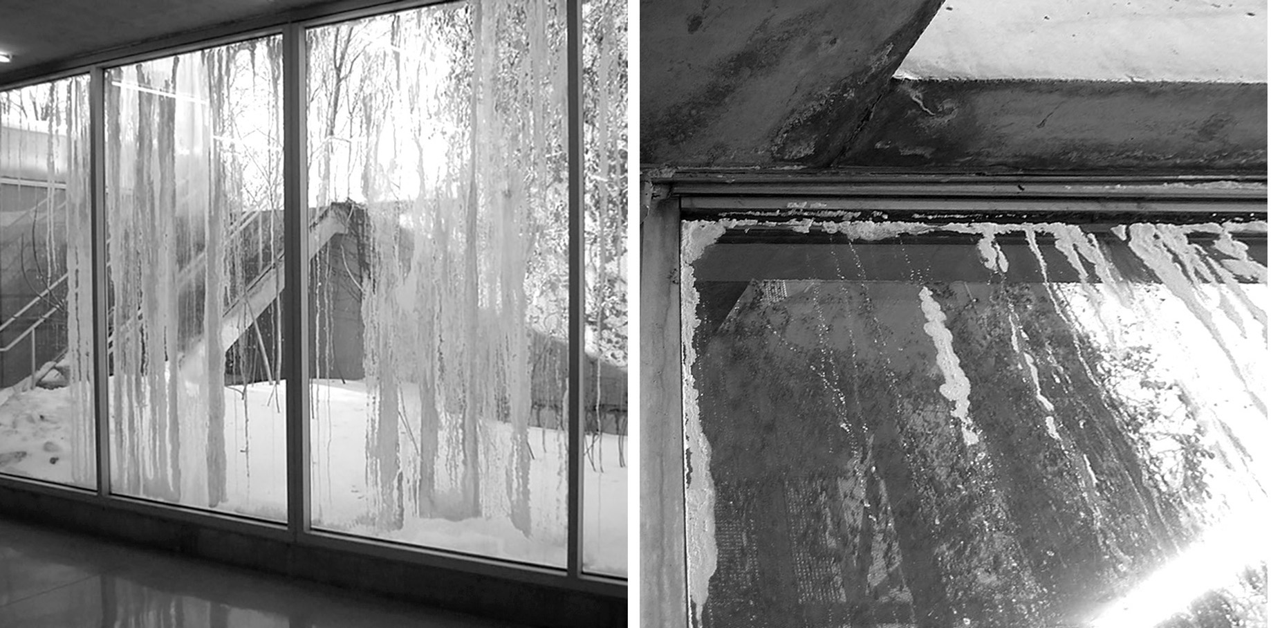
Figure 10.9. The Bibliowicz Gallery windows at Milstein Hall were covered in efflorescence due to water leaking through the plaza deck above (March 2015).
It turns out that these problems were the result of numerous errors in the design of the plaza deck slab that forms the roof of the gallery space. Such a slab deck is really a roof, and such decks need to be designed as a roof, incorporating the following six characteristics:7
The design must provide drainage below the traffic surface, including a drainage gap above the water control layer, that is, above the roof membrane.
The roof membrane must slope to a drain.
The design should really incorporate a double drain, i.e., a second drain from the traffic surface.
Insulation should be installed above the roof membrane with a drainage mat above and below it.
All drainage should slope away from the edge of the deck, towards an interior drain.
The water control layer of the deck must be connected to the water control layer in the walls of the adjacent existing building, Sibley Hall. Of course, the load-bearing brick wall of Sibley Hall has no water control membrane, so it is important (and difficult) to properly flash this wall-deck intersection.
Of these six guidelines, only one was correctly implemented in Milstein Hall—the fourth one requiring insulation above the roof membrane with drainage mats above and below the insulation.8 A series of images screen-captured from my low-resolution video clips, part of my online critique of Milstein Hall,9 shows a roof membrane, drainage mats, and insulation being placed above a perfectly flat structural slab; after that, a topping slab—also perfectly flat—is placed above the insulation and drainage mat (fig. 10.10).
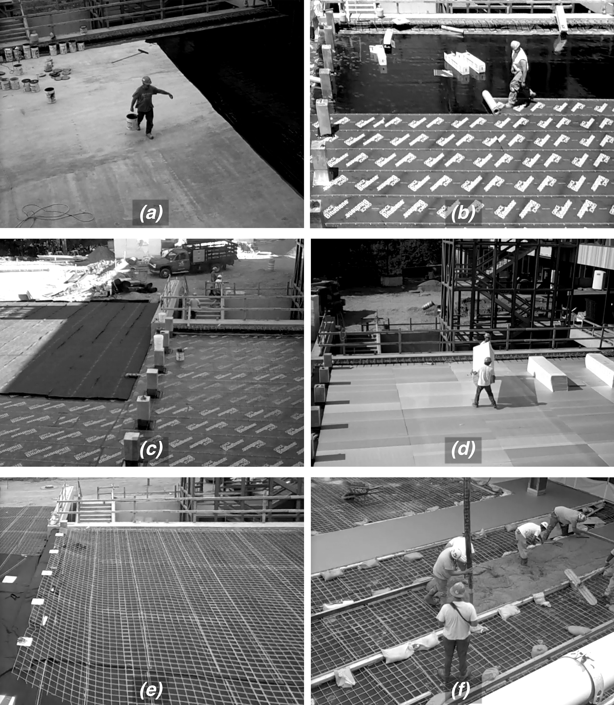
Figure 10.10. The plaza roof deck at Milstein Hall was constructed over a perfectly flat structural slab. All subsequent layers were also perfectly flat: (a) initially, some sort of mastic or primer was applied to the structural concrete slab; (b) next, a waterproof membrane was rolled out over the primer/ mastic; (c) a drainage mat came next; (d) then three layers of rigid insulation were placed over the drainage mat; (e) a second drainage mat was placed over the insulation, along with welded wire mesh reinforcement for (f) the final perfectly flat layer, a concrete topping slab.
But the other five requirements for a slab deck over heated space were simply not specified in the design drawings and therefore were not implemented: there was no explicit drainage gap below the traffic surface; not only was the deck designed with no slope, but there was no drain specified for the plaza; with no drain specified, there could be no double-drain; because the water control layer did not slope, and therefore did not slope away from the edge of the deck, water was able to enter the fascia above the gallery windows and threaten the integrity of the concrete while staining the windows below; and finally, the intersection of the roof membrane and the brick wall of Sibley Hall was not properly flashed.
As it turned out, there was also an additional problem with the structural design of the slab deck itself—for some reason, this concrete slab experienced exceptionally large, and unexpected, deflections. In fact, the deflection may possibly have been the reason that the rotating gallery wall directly below was taken apart and rebuilt (fig. 10.11).
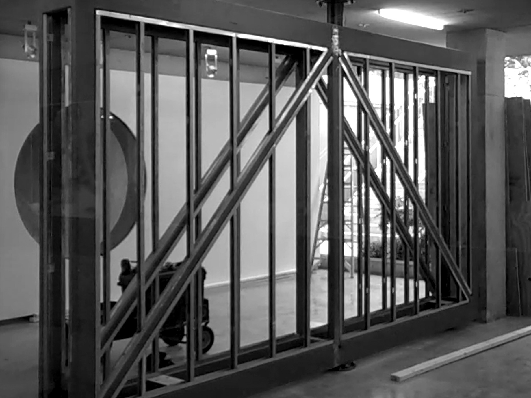
Figure 10.11. The rotating wall in Milstein Hall's Bibliowicz Gallery was taken apart and reconstructed, shown here with the wall finishes removed in the summer of 2012, possibly because of damage caused by excessive deflections in the concrete slab above.
Because of the slab's deflected shape, water would pool at its center, and remain there long after any rain had stopped (fig. 10.12).
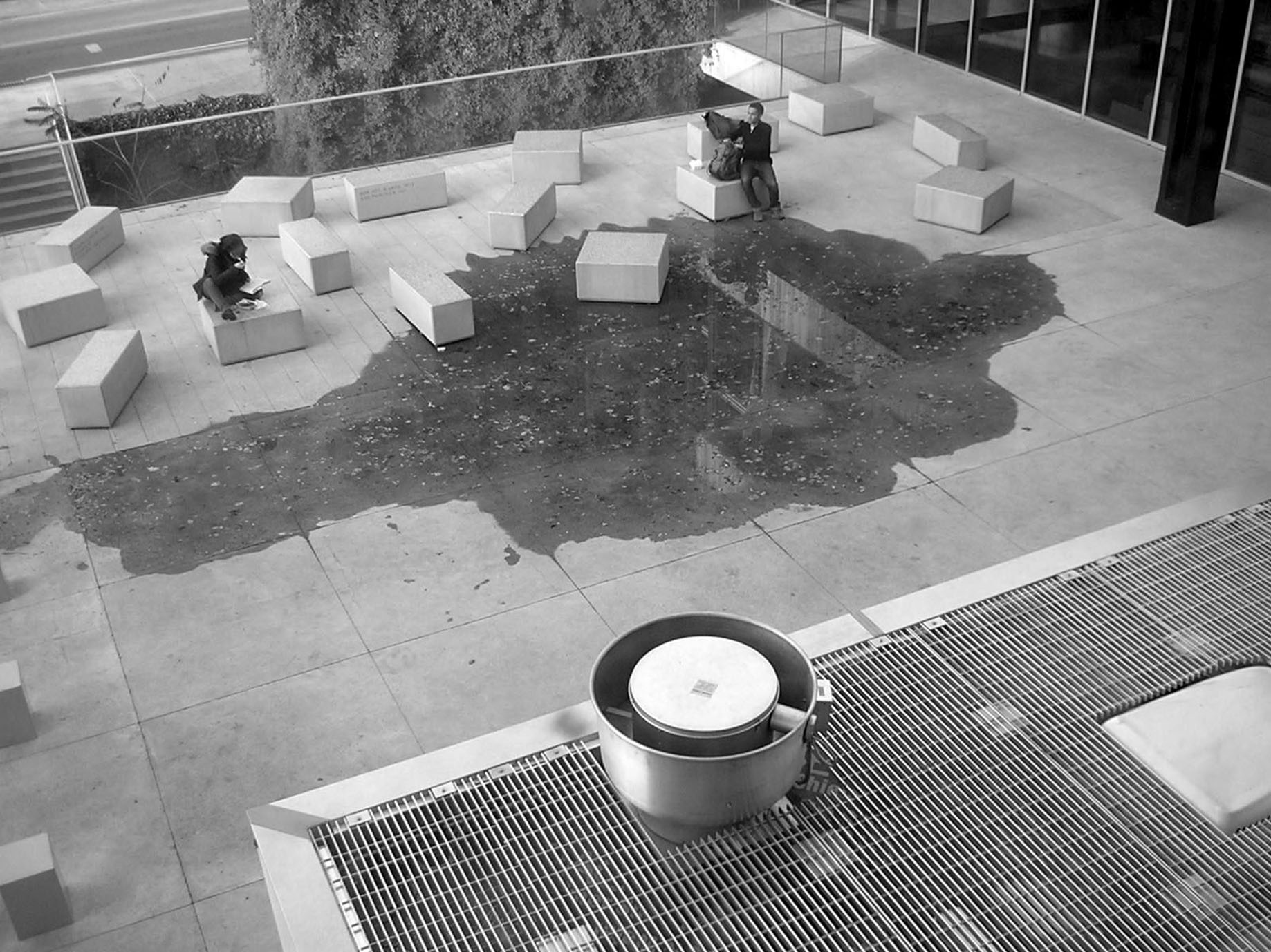
Figure 10.12. Water would pool at the center of Milstein Hall's plaza long after any rain had stopped, for two reasons: first there was no drain; and second, the slab deflected so that rainwater tended to move to the center of the concrete deck's span.
However, this very problem of slab deflection actually allowed Cornell to retroactively address some of the major mistakes from the original design. Because of the unintended sloping of the deck, it became possible, in the summer of 2015, to retroactively install a new drain at the low-point of the deflected slab which would carry excess water away from the edge of the deck—three years after the initial attempt at remediation. The topping slab was cut at the approximate low point of the plaza, caused by the unintended deflection, and most of the rigid insulation was removed to accommodate a linear channel, sloping to a new drain (fig. 10.13).
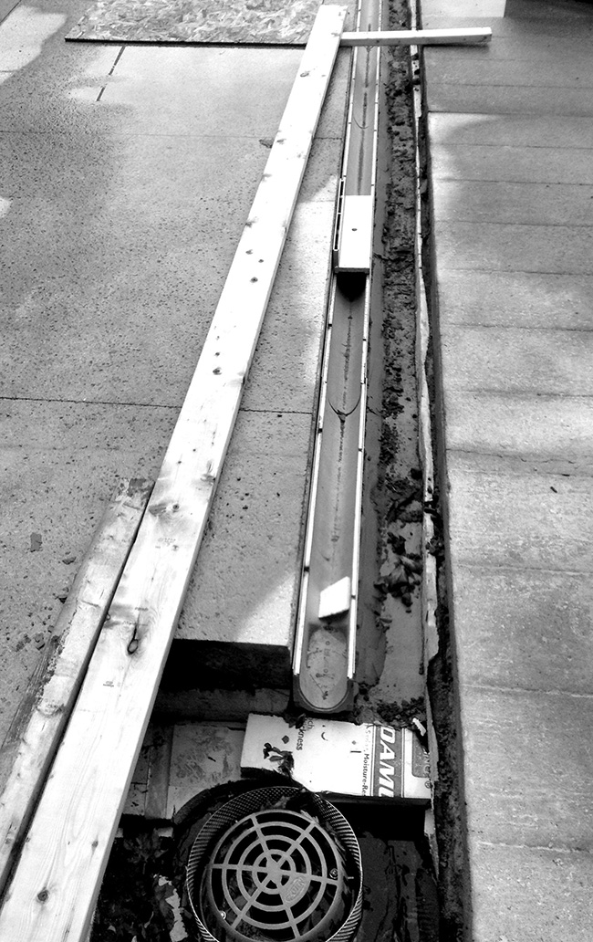
Figure 10.13. The topping slab of Milstein Hall's plaza deck was cut at the approximate low point and most of the rigid insulation was removed to accommodate a linear channel, sloping to a new drain.
A hole was drilled through the concrete deck so that the drain pipe could enter the gallery below, find its way through an existing gallery wall, and continue into the basement slab, where it was connected to a storm sewer pipe below grade that happened to be in the vicinity (fig. 10.14).
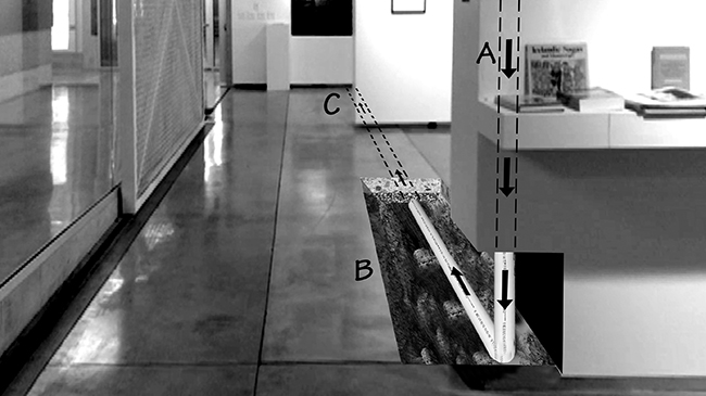
Figure 10.14. Rainwater from the plaza above now enters the Bibliowicz Gallery through a new drain connected to a pipe drilled through the concrete deck above and threaded through the fixed gallery wall at A, after which it continues through the basement slab at B, eventually connecting with a storm sewer pipe at or near C. The patched basement slab can be seen with a lighter surface finish. Image photoshopped by the author to reveal hidden pipe.
Meanwhile, additional reconstruction was undertaken at the edges of the plaza, over the gallery windows and also on the western edge near Sibley Hall. Workers used concrete saws and jackhammers to remove most of the perimeter fascia above the gallery windows (fig. 10.15) and a metal drip edge was installed over the one previously installed during the initial reconstruction of the gallery wall—where the bent metal water stop had been installed into a kerf cut into the concrete three years earlier.
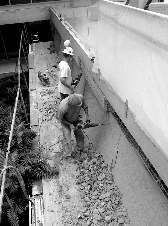
Figure 10.15. Workers remove most of the concrete fascia of Milstein Hall's Bibliowicz Gallery.
A waterproofing membrane was joined to flashing, new insulation was placed over this new air/water barrier, and another piece of stainless-steel was installed over the drip edge to form a base, or pour-stop, for the reconstructed concrete fascia while also allowing water entering the concrete from above to exit by traveling between the two pieces of metal (fig. 10.16).
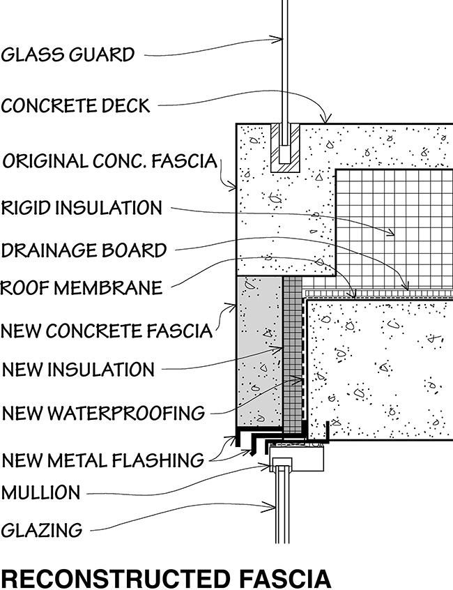
Figure 10.16. The second gallery reconstruction, in 2015, removed and replaced much of the concrete fascia, installed new waterproofing and insulation behind the new fascia panel, and placed two pieces of metal flashing above the bent metal water stop that had been inserted into the concrete ceiling above the mullion in 2012. Water entering the slab from the deck above and working its way down to the mullion will now be directed between the two pieces of flashing to the exterior. This is a speculative and schematic section based on my observations of the reconstruction that occurred in 2015.
One can see that when it rains, the new drain doesn't exactly capture all the surface water. Puddles always remain because a slope was never actually built into the design (fig. 10.17).
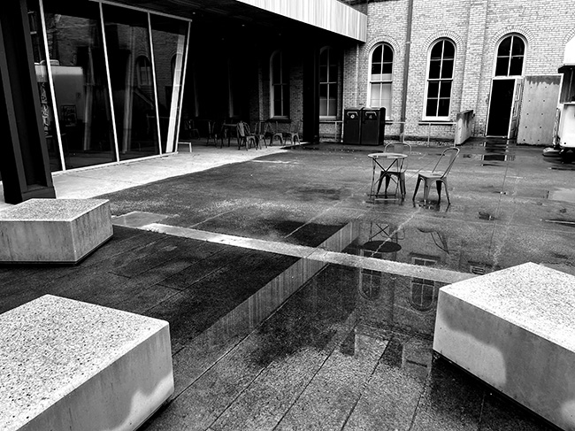
Figure 10.17. Puddles still form, and remain, on the Milstein Hall plaza because the slope caused by the slab's unintended deflection does not create a consistent low point that aligns with the position of the linear drain that was added later, visible in the middle of the image.
More importantly, even after this substantial renovation of the plaza deck and gallery fascia, the underlying problems have not been resolved, as of this writing in 2023. Water still finds its way through cracks in the concrete (fig. 10.18), and may well be pooling under the insulation, since there is still no primary drain at the level of the waterproofing membrane. If so, this water could be damaging the rigid extruded polystyrene insulation above the waterproof layer. According to Sharif Asiri, "water can still be absorbed into the gaps between each bead. Long term studies on rigid XPS (extruded polystyrene) reveal that in below grade applications, the area where rigid insulation is most likely to get wet, XPS absorbs 19% of its weight in water, resulting in a 48% reduction in R-value."10
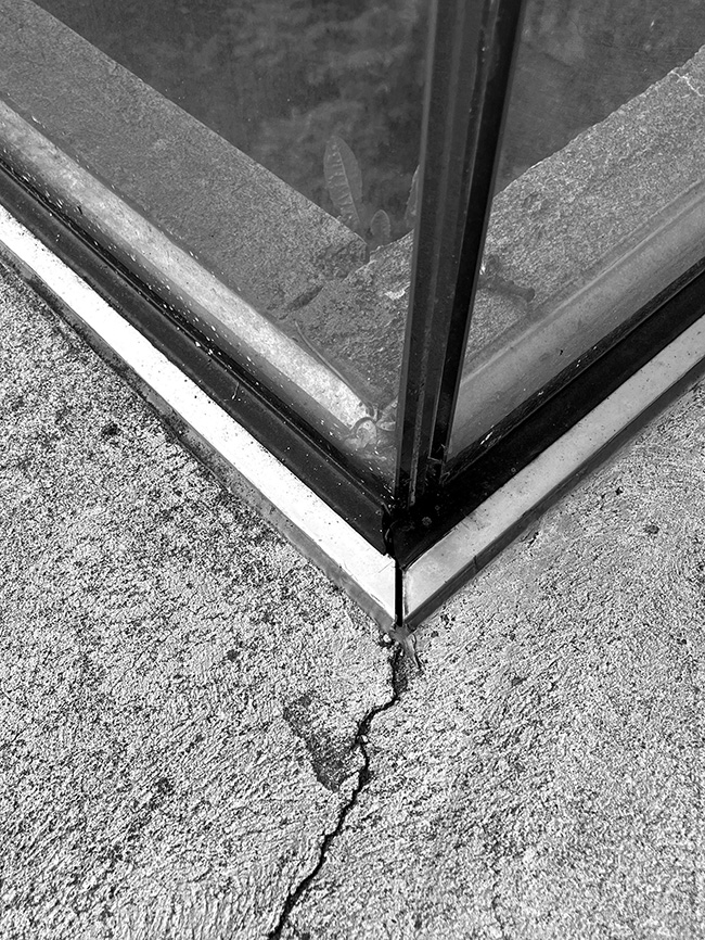
Figure 10.18. Water can enter the concrete slab of the plaza deck through cracks in the concrete and openings in the glass guard inserts around the sunken garden, above the below-grade gallery. (Image taken May 2023.)
And the same mechanism which permitted water to enter the slab and work its way into the fascia remains unchanged, resulting not only in dampness and efflorescence on the fascia, but also—something I noticed for the first time in 2023—serious spalling of the concrete at the edge of the plaza deck (fig. 10.19).
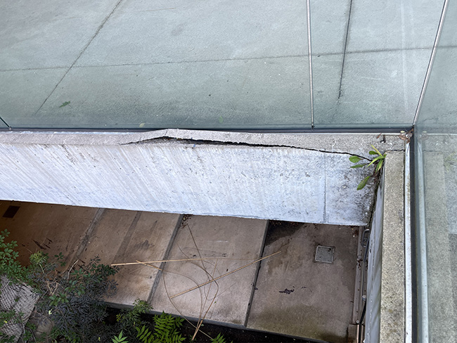
Figure 10.19. Even after substantial renovation of the gallery fascia and plaza deck in 2015, major spalling of concrete is occurring at the fascia-deck intersection. (Image taken July 2023.)
Water also picks up some rather nasty artifacts as it enters the concrete, passes through both intended and unintended channels, and drips down to the sill below (fig. 10.20).
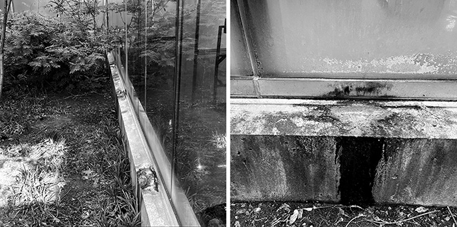
Figure 10.20. Water also picks up some rather nasty artifacts as it enters the concrete, passes through both intended and unintended channels, and drips down to the gallery sill below. (Image taken May 2023.)
Water leaking through basement roofs: electrical panel box
More leaks were discovered through the ground-level concrete slab under the arcade between Milstein and Sibley Hall that is adjacent to the plaza deck. Apparently, this leak, into the electrical room below, had been active for years, but only in 2019 was it being investigated and repaired. One can see electrical conduit penetrating the waterproofing layer under the rigid insulation that is, in turn, under the concrete topping slab of the arcade (fig. 10.21).
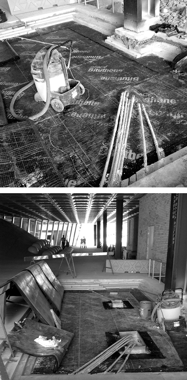
Figure 10.21. Electrical conduits are cast into the roof deck concrete slab under Milstein Hall's arcade; once over the basement electrical room, they penetrate through the structural concrete slab below the topping slab with only nominal attention to waterproofing, providing a pathway for rainwater to enter the electrical room (top). To repair this condition, the concrete topping slab, insulation, and drainage mats were removed so that metal "dams" could be placed around the areas where conduit penetrations occur (bottom). The drainage mats and insulation were then re-installed, and new concrete was cast to repair the topping slab.
These penetrations provide a convenient pathway for rainwater to enter the electrical room below. Rainwater gets into this covered location because the concrete slabs of the arcade and adjacent plaza were designed to be perfectly flat surfaces, without any sort of slope for drainage. The actual—as-built and unintended— slopes of these concrete slabs directed rainwater into the covered arcade directly above the electrical room.
Water leaking through vegetated roof
Leaks began to be noticed on the upper level of Milstein Hall, through the roof, soon after the building was occupied in 2011, continuing for the following decade, with no solution in sight (fig. 10.22).11
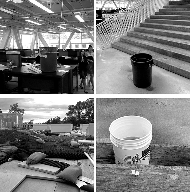
Figure 10.22. Trash cans appeared in Milstein Hall's cantilevered second floor design studios soon after the building was occupied in 2011, placed strategically to catch rainwater leaks from the vegetated roof above (top left), both through skylights and at the intersection of Rand Hall and Milstein Hall. Leaks continued in 2015 (top right), triggering a major roof repair that lasted for at least two years (bottom left), during which time sedums, engineered soil medium, insulation, drainage mats, and protection layers were removed and stockpiled elsewhere on the roof. This major repair also proved unsuccessful, as leaks continued in some of the same places during the fall of 2022—at the stepped auditorium (bottom right) and at the intersection of Rand Hall and Milstein Hall (not shown).
As is common with roof leaks, the Milstein Hall leaks appear to be related to defects in the flashing strategy and/or execution both at skylights as well as at the joint between the roof and masonry walls of existing buildings—Rand Hall, in this case. Skylights appeared to be designed with large gaps, discontinuous insulation, and a reliance on sealants to close openings in aluminum cover plates (fig. 10.23).
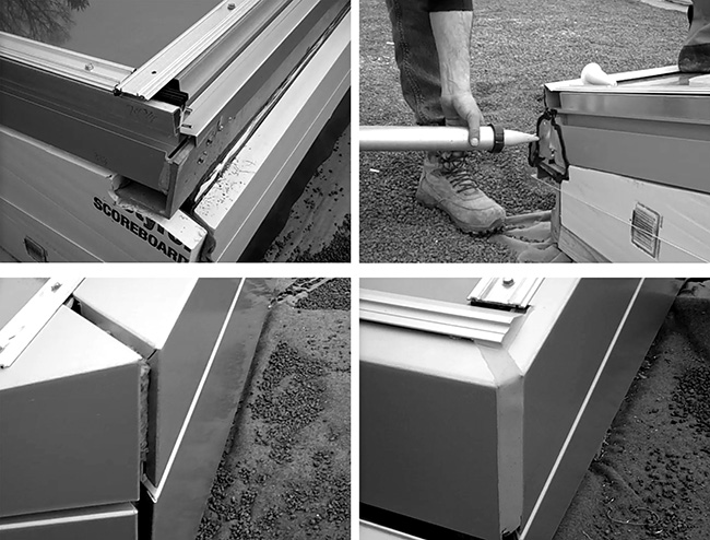
Figure 10.23. Skylights in Milstein Hall have large openings where metal enclosure panels meet at the corners (top left); at some of these intersections, pieces of metal were "glued" in place with some sort of adhesive sealant (top right). Aluminum cover plates came together with mitered joints at the corner, leaving large gaps (bottom left) that were filled with sealant (bottom right).
At the intersection of Rand Hall and Milstein Hall, the seismic joint between the two buildings relies on reglets—minimal saw-cut openings in the horizontal brick mortar joints of Rand Hall—that not only are unreliable because water can penetrate around such flashing through cracks between mortar and brick (fig. 10.24), but especially because, in this case, the reglet and flashing need to negotiate tricky geometries where brick protrudes to cover Rand Hall's steel columns (fig. 10.25). This is a complex three-dimensional condition that is represented in the Milstein Hall working drawings as a simple two-dimensional section, as if the reglet flashing—even if it were effective in its two-dimensional incarnation, something far from certain—could somehow be fashioned into this more complex three-dimensional form based solely on the goodwill and expertise of the installers.
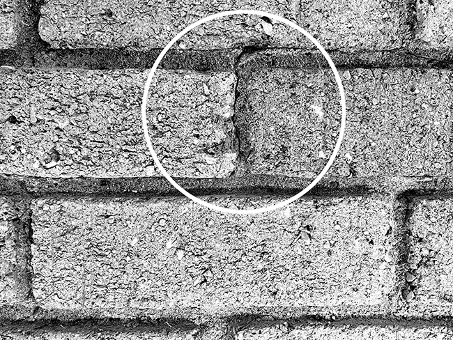
Figure 10.24. This detail of Rand Hall's facade shows a typical crack between brick and mortar through which water can enter the wall, bypassing flashing in saw-cut reglets.
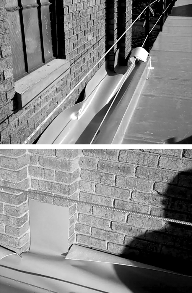
Figure 10.25. The intersection of Milstein Hall's roof with the brick cladding of Rand Hall was sealed with a seismic joint, similar to the joint at Sibley Hall illustrated schematically in Figure 9.6. Here, Milstein Hall's PVC roof membrane is shown prior to the creation of a reglet in the brick wall and the completion of a seismic joint (top) and at the challenging geometry where brick protrudes to cover Rand Hall's steel columns (bottom).
An additional factor in Milstein Hall's persistent roof leaks is the virtual flatness of the roof, discussed earlier in terms of various conceptual fictions, distortions, and half-truths that have been promoted by the architects. The ultra-low slope of the roof may well have been partly responsible for the ongoing problem of leaks that has plagued the building since it first opened and that has continued for at least twelve years since, even after a substantial re-roofing operation that began in 2015 and took more than two years to complete. The flatness of the roof is not literal, since the roof has a topping slab that slopes to gutters along the edge of Sibley Hall and also to several internal roof drains. But the slope is insufficient—not even close to the minimum code-required two percent slope for single-ply thermoplastic roofing, i.e., "a minimum of one-fourth unit vertical in 12 units horizontal."12 As can be seen in Milstein Hall's roof drainage plan, redrawn schematically in figure 10.26, the horizontal distance between the roof high point and the roof drain is 50 feet (15.24 m) yet the vertical change in elevation is only 2-5/8 inches (66.7 mm). To comply with best practices (and with the requirements of the New York State Building Code for a two percent slope), this change of elevation should have been a minimum of 12-1/2 inches (317.5 mm)— almost five times greater than what was actually provided. This is evident in figure 10.27, which shows a roof slope being created with a topping slab poured over the flat structural concrete slab; the wood guide for the screeding operation is virtually horizontal!
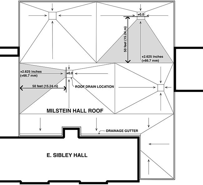
Figure 10.26. Milstein Hall's roof drainage plan, drawn without the skylights for clarity, shows a change in vertical elevation almost five times less than what is required by the New York State Building Code.
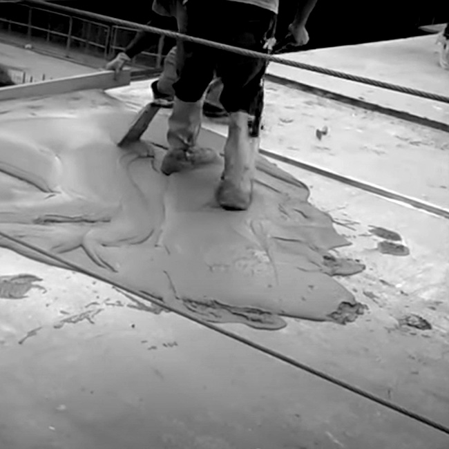
Figure 10.27. Milstein Hall's topping slab is shown being poured over the flat structural slab. The wooden guide for the screed has almost no inclination and certainly not a two-percent slope.
I can't say for sure why the architects chose to defy best practices and create a virtually flat roof with inadequate slope for drainage, but my best guess is that the decision was ideological rather than logical. The proposition that this roof is a facade—a canvas on which a colored circular sedum pattern can be metaphorically painted—is certainly compatible with the idea that such a canvas should be flat. But the Milstein Hall canvas isn't literally flat. The fact that it has a nominal, though inadequate slope, shows that the architects were aware that roofs must slope to drains. What really caused the slope to be inadequate and the vegetated roof to be "extensive" rather than "intensive"—i.e., to have only about 2 inches (50 mm) of engineered soil medium supporting its sedum plants—almost certainly derives from Milstein Hall's initial diagrammatic cartoon and its spatial constraints, discussed earlier. Once a decision was made to place Milstein Hall's new second-floor plate, lifted off the ground, at the intersection of the east-west and north-south conceptual zones discussed in chapter 7 and shown in figure 7.1, the second floor needed to be high enough to align with (and connect to) the floors of Sibley Hall and Rand Hall, while the roof of Milstein Hall needed to be low enough so that it would fit under the existing and historic third-floor windows of Sibley Hall. With these self-imposed constraints, there simply wasn't enough room to raise the height of the roof coping to accommodate an adequate (and required) slope for the roof membrane without coming into conflict with the third-floor windows in Sibley Hall (fig. 10.28).
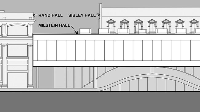
Figure 10.28. The second floor of Milstein Hall needed to be high enough to align with (and connect to) the second floors of Sibley Hall and Rand Hall, while the roof of Milstein Hall needed to be low enough so that it would fit under the existing third-floor windows of Sibley Hall.
Notes
1 Karen Warseck, "Why Sealant Joints Fail," BuildingDiagnostics.com, accessed online Aug. 15, 2013 (no longer available).
2 "Regletting Does Not Work—Saw cutting a 'notch' or 'reglet' into the brick and inserting a 'counter flashing' will not do the trick. No chance." Lstiburek, "BSI- 122: If You Want to Save Cash … Flash…"
3 Wikipedia, s.v. "Efflorescence" last modified November 12, 2022, 06:49 (UTC), here.
4 Sutan and Hamdan, "Efflorescence Phenomenon," 748.
5 Wikipedia, s.v. "Efflorescence."
6 Jonathan Ochshorn, "Milstein Hall Nonstructural Failure: Gallery Leaks," August 28, 2013, here.
7 Lstiburek, "BSI-051: Decks—Roofs You Can Walk On."
8 Milstein Hall's working drawings only called for one drainage board, below the insulation on the roof deck above the gallery, although my videos show an additional membrane or board also placed on top of the insulation boards.
9 I made two videos to illustrate and explain problems with Milstein Hall's flat plaza deck, the gallery beneath, as well as remedies undertaken by Cornell. See Jonathan Ochshorn, "Milstein Hall Nonstructural Failure: Gallery Leaks" (note 6) and Jonathan Ochshorn, "Milstein Hall Nonstructural Failure: Gallery Leaks (2015 update)," here. Much of this section, about the gallery water problems and the flat plaza roof deck, is based on my commentary in these videos.
10 Sharif Asiri, "Can Rigid Insulation Get Wet?", Asiri Designs, accessed May 25, 2023, here.
11 I made several videos that illustrate and explain the construction of Milstein Hall's green roof as well as some of the roof leaks and attempted repairs. See Jonathan Ochshorn, "The Construction of Milstein Hall Part 10—Green Roof," here, Jonathan Ochshorn, "Milstein Hall Nonstructural Failure: Roof Leaks," here, and Jonathan Ochshorn, "Milstein Hall Nonstructural Failure: More Roof Leaks," here.
12 "1507.13 Thermoplastic single-ply roofing." ICC, New York State Building Code, 2002, 277.
contact | contents | bibliography | illustration credits | ⇦ chapter 9 |