contact | contents | bibliography | illustration credits | ⇦ chapter 8 |
9. THERMAL CONTROL

Controlling heat flow (energy) is a basic requirement of building design, if not architectural design. The idea that the latter is endangered by the former is certainly a legitimate fear—given the increasingly perverse interest in understanding architecture as a heroic project—yet the outcome of such an attitude is always disheartening for both architect and client.
What follows is not necessarily an all-inclusive list of such thermal control failures at Milstein Hall. Without official access to such information, I must rely primarily on random observations of the building.
Thermal bridging at stone cladding
Attachment of stone veneer panels, based on approved shop drawings, differed considerably from contract document details—with unintended consequences for thermal bridging and heat loss. Specifically, the original stone anchoring system consisted of a two-part adjustable bracket system that penetrated the thermal control layer, i.e., the rigid insulation, only at the four points where steel anchors, grouted into the stone cladding panels, attached to the brackets (fig. 9.1a). This was replaced by virtually continuous horizontal steel angles that interrupt the rigid insulation, creating a highly conductive pathway, i.e., a thermal bridge, for heat loss or heat gain (fig. 9.1b).
In these sections, it's hard to see the extent to which the steel angles interrupt the rigid insulation, but the image screen-captured from one of my Milstein Hall construction videos (fig. 9.2 left) makes this clear. A better strategy, even when long or continuous shelf angles are used, is to detail them so that they "stand off" from the structural slab (fig. 9.2 right). In this way, the thermal control layer (insulation) can extend behind the shelf angle, minimizing thermal bridging.
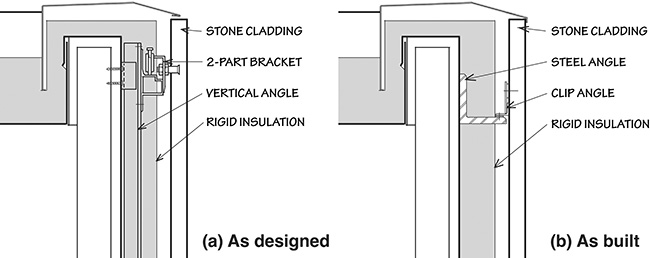
Figure 9.1. The original design (a) shows an adjustable 2-part bracket system which minimizes thermal bridging; the detail as built (b) replaces this "hi-tech" system with a "low-tech" assemblage of angles and clip angles which interrupt the continuity of the rigid insulation, creating a significant thermal bridge.
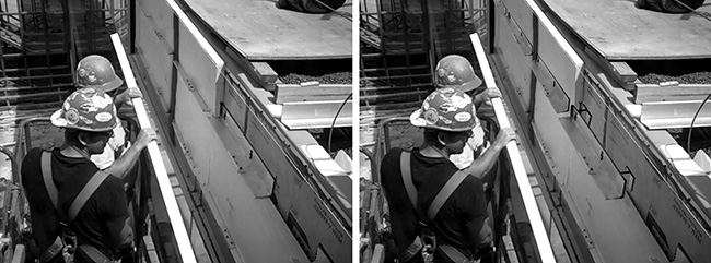
Figure 9.2. A significant thermal bridge can be seen in this construction photo of Milstein Hall (left), with horizontal steel angles, to support stone cladding panels, interrupting the thermal control layer, i.e., the rigid insulation. I've revised this screen-captured image to illustrate how a "stand-off" works (right): the horizontal angle would need to be moved 2 inches (50 mm) away from the sheathing and air barrier so that rigid insulation can be placed behind the steel angle, minimizing the thermal bridging.
Bollards as thermal bridges
Bollards were installed above below-grade, heated, spaces in Milstein Hall in order to protect pedestrians from vehicles in a loading area that is situated directly above those heated spaces. Inexplicably, these bollards are attached, not to the concrete sidewalks on which they appear to sit, but to the structural concrete for the underground portion of Milstein Hall below. Construction images show the bollards installed directly over the structural concrete slab, above heated and occupied below-grade space (fig. 9.3 top). Rigid insulation boards are then placed around the bollards (fig. 9.3 bottom), leaving a series of gaps through which heat can escape.

Figure 9.3. Bollards are installed directly on the structural concrete slab above occupied and heated space (left); insulation boards are then placed around the bollards (right).
The bollards interrupt not just the insulation boards, but also the continuity of waterproofing that has been installed above the structural concrete slab to which the bollards are attached.1 As a result, there is a risk that any vehicle-bollard collision could dislodge the waterproofing membrane which is flashed onto the surface of the bollard below (fig. 9.4). Because all the connections are below grade, it would be impossible to know whether any damage has occurred until water leakage, or its many manifestations, appears in the space below.
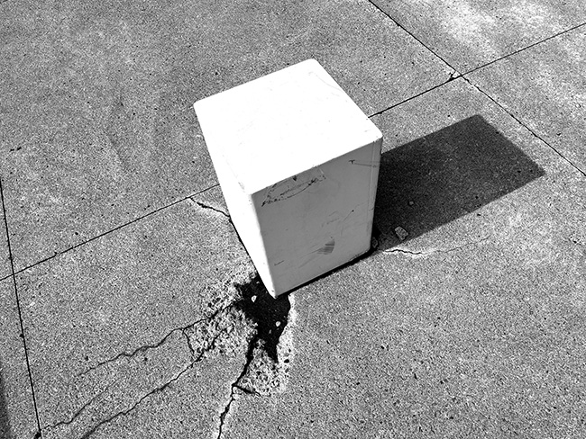
Figure 9.4. Concrete cracking and slight displacement of the bollard suggests a vehicle-bollard collision that may have compromised the waterproofing hidden below grade.
The discontinuous insulation layer results in thermal bridging, as heat from the spaces below is conducted directly through the concrete slab and bollards above, which have interrupted all three layers of rigid insulation placed over the structural slab. This shows up, quite artistically, as a series of almost perfect circles surrounding each of the bollards after it snows (fig. 9.5 top). A photoshopped cut-away version of the same photo (fig. 9.5 bottom) shows how the bollard is fastened to the structural slab, penetrating three layers of rigid insulation, and thereby creating a perfect thermal bridge connecting below-grade heated spaces with the exterior loading area.
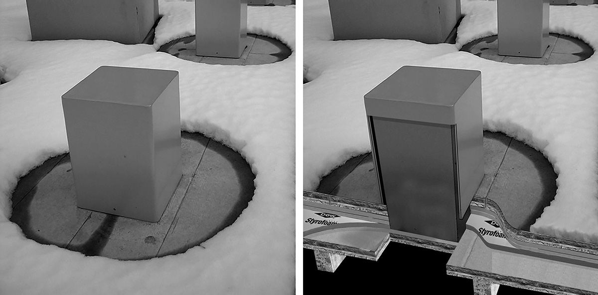
Figure 9.5. Bollards placed over Milstein Hall's below-grade heated space penetrate all three layers of below-grade rigid insulation, causing unimpeded heat loss from those below-grade spaces (right, photoshopped cut-away image—waterproofing and drainage layers not shown); the circular areas of melted snow around each bollard (left, original photo) attest to the heat loss through the bollards from the occupied space below.
Thermal bridging through seismic joints
All buildings must be designed to withstand an assortment of load combinations, including live and dead loads (which act vertically on the structure) as well as earthquake and wind loads (which act predominantly in a horizontal direction). While live and dead loads are essentially added together, since it is certain that dead loads will be present when live loads are acting on the structure, the same is not true for earthquake and wind loads: the probability of a structure experiencing high wind and earthquake forces simultaneously is so low that designers are permitted to determine relevant internal forces and bending moments based on load combinations that include wind and earthquake loads, but not both at the same time.
Clearly, there are areas in the world where earthquake forces almost always govern the design of lateral-force-resisting systems—e.g., parts of Chile, California, Alaska, Japan, and other regions along the seismically active Pacific rim—whereas lateral-force-resisting systems for buildings in places like Ithaca, New York, are generally designed on the basis of wind loads. Milstein Hall is an exception. Unlike probably every other building at Cornell, or in the City of Ithaca, Milstein Hall's structural design is governed by seismic loads rather than wind loads. This anomalous situation has been brought about by a perfect storm of unusual design decisions: the cantilever over University Avenue has made the building's structure extraordinarily heavy; this extremely heavy structure is then raised up in the air on steel columns that resist horizontal forces with rigid (moment) connections rather than with shear walls or diagonal braces of any kind; and the above-ground volume of Milstein Hall is flattened into a large second-floor plate sitting above a smaller glass enclosure for the entry and below-grade spaces. What this means is that—relative to the volume and weight of the building—the surface area exposed to horizontal wind loads is small. But the placement of an extremely heavy superstructure on relatively few columns creates a classic inverted pendulum or "soft story"—the very worst condition for seismic resistance. So with a raised and heavy second floor highly susceptible to seismic ground motion and relatively little vertical surface area affected by wind loading, it is not that surprising that the lateral-force-resisting system is governed by seismic loads. And the seismic drift or lateral deflection of the second-floor plate, combined with whatever lateral movement is computed for Sibley and Rand Halls, has made it necessary to provide a flexible "seismic joint" with a width of 5 inches (127 mm) so that flexible Milstein Hall and relatively stiff Sibley and Rand Halls do not pound into each other during a seismic event (fig. 9.6).
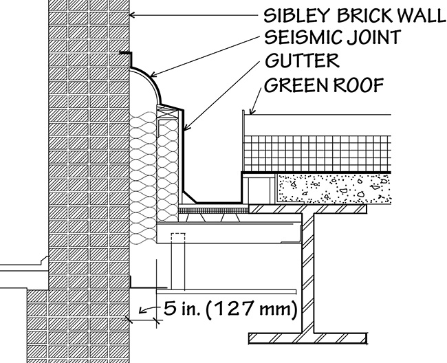
Figure 9.6. The 5-inch-wide seismic joint as detailed between Milstein and Sibley Halls (similar for Rand Hall).
The seismic joint, as built, appears to be different from the detail, in that no curved profile is evident (fig. 9.7). It is difficult to say what exactly was fabricated and installed, and in what manner it was designed to accommodate movement, if at all.
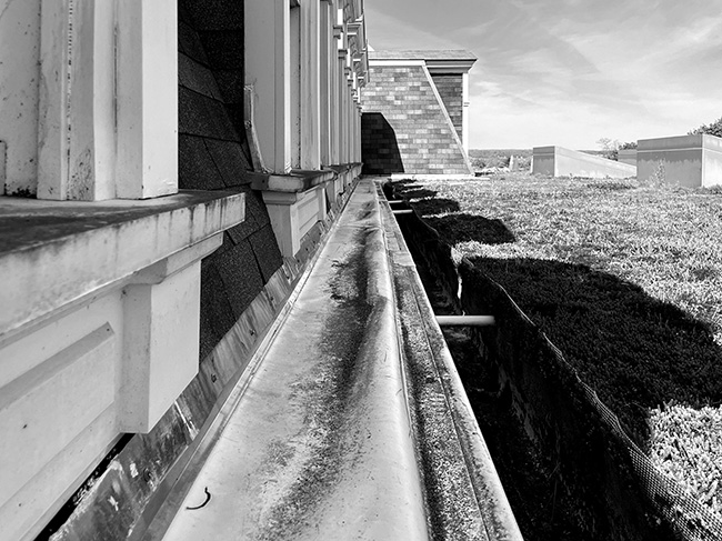
Figure 9.7. Milstein Hall's seismic joint, as built at the edge of Sibley Hall, differs from the circular profile shown in the working drawings.
The seismic joints have also, apparently, been kept free of insulation, not stuffed with batt insulation as shown in the detail. I had emailed the College of Architecture, Art, and Planning's project liaison in November 2009, remarking that "…the 5-inch space immediately below the curved expansion joint cover is filled with 'batt insulation,' but not otherwise protected against vapor intrusion from the interior space below… It may be that, even without humidifying the Milstein space, there would be high enough relative humidity (generated by building occupants) that such air, working its way up into the insulation, would reach the colder surface of the expansion joint cover and condense, wetting the insulation, and potentially causing other nasty problems during the winter months." The project manager replied in January 2010 that he "has looked at the issue … and discussed it with team members. It is still a bit on the back burner since we have so many other pressing issues that need to be dealt with immediately. Be assured that we will close the loop with you on this issue." Well, he never "closed the loop" with me, but I was told much later that the seismic joints were, in fact, uninsulated, constituting one more thermal bridge in the building. This can be seen at the intersection of Milstein and Rand Halls (fig. 9.8), which has no cover plate hiding the thermal bridge, unlike the situation at the intersection of Milstein and Sibley Halls, where a metal plate covers the joint.
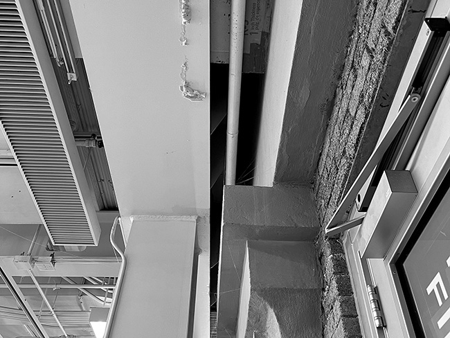
Figure 9.8. Seismic joints between Milstein Hall and Rand Hall create a 5-inch (127 mm) uninsulated gap where the buildings come together.
Thermal bridge through skylight curbs
Skylight curbs were cast in reinforced concrete and interrupt the three layers of rigid insulation on the roof deck under the green roof plantings. Before rigid insulation was adhered to these concrete curbs, circles of melted snow could be seen on the roof around the skylights (fig. 9.9 top left); while the insulation improved the thermal performance, one can see that discontinuities in the thermal control layer (fig. 9.9 right) still melt the snow immediately adjacent to the skylight curbs (fig. 9.9 bottom left).
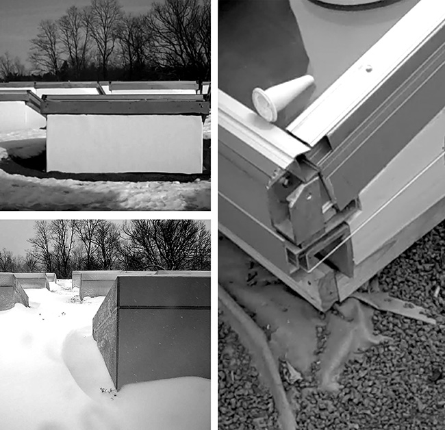
Figure 9.9. Effects of heat loss can be seen in circles of melted snow around uninsulated skylights during construction (top left); insulation adhered to concrete skylight curbs is not continuous with horizontal insulation placed over the roof deck, creating thermal bridges (right); and because the reinforced concrete skylight insulation is not continuous, the effects of heat loss (thermal bridging) can be seen in the adjacent depressions within the otherwise even bed of snow (bottom left).
Inside Milstein Hall, one can see that snow melts from much of the skylights in the winter, as would be expected, due to the increased heat loss through the glass compared with the rigid insulation under the green roof (fig. 9.10).
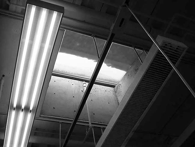
Figure 9.10. Snow melts on the Milstein Hall skylights, attesting to heat loss through these openings. The rectangular fixture to the right of the skylight is not illuminated because it is not a lighting fixture; rather, it is a chilled beam unit (for cooling) that was designed with the same enclosure finishes and dimensions, and arrayed within the same geometric grid, as the lighting fixtures.
From the standpoint of energy consumption, there is a potential trade-off, since daylight within the space is improved, as described on Cornell's "Innovative Design" webpage for Milstein Hall: "Three sizes of skylights are arranged in a radial pattern on the roof with the larger ones at the center and smaller ones toward the perimeter of the building. This creates consistent natural light levels across the entire second floor studio space."2 An evaluation of the energy-saving benefit of daylighting compared with the energy-losing heat loss through the glass was presumably never done and, if it was done, certainly was never made public. But whatever the cost-benefit outcome of such a calculation (and the potential for energy savings is unlikely), it is rendered moot since electric lights are almost always on—triggered by motion sensors— whether or not adequate daylighting is available.
Thermal bridging through steel columns
Thermal bridging, caused by steel columns that penetrate Milstein Hall's insulated soffit below the second floor, is not inconsequential. Even without a sophisticated thermal analysis, one can make a rough estimate of the energy penalty by comparing the heat loss with studio floor column penetrations to the heat loss through an insulated floor without column penetrations.
As can be seen in figure 9.11, there are fourteen exterior columns holding up the second-floor plate; each of these W14×605 wide-flange shapes has a cross-sectional area of 178 square inches (0.115 square meters). The column labeled No. 4 in the plan appears to be inside the first-floor enclosing walls, but is actually exposed to the elements above the concrete dome and so contributes to thermal bridging—not only with respect to the second-floor studios, but also the Crit Room space below (fig. 9.12).
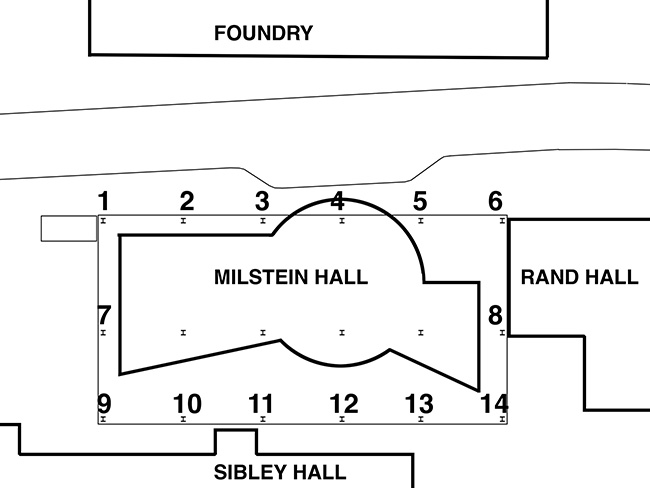
Figure 9.11. This schematic first-floor plan shows all 18 first-floor columns that support the large second-floor plate. Of these 18 columns, only four are within the building enclosure at the first-floor level; 14 are outside and contribute to thermal bridging.
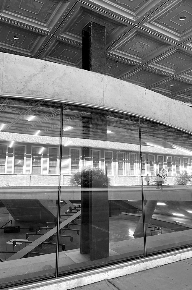
Figure 9.12. Exterior column No. 4 penetrates both the second-floor soffit above and the Crit Room space below.
The total uninsulated steel-column area penetrating the studio floor is therefore 14 × 178 = 2492 square inches or 17.3 square feet (1.6 square meters). These large column sizes penetrate the insulation under the second-floor composite steel-concrete deck, since they are welded to the bottom chords of story-height hybrid trusses that have stiffener plates reproducing the dimensions of, and aligning with, the column flanges (fig. 9.13).

Figure 9.13. Milstein Hall's exterior columns, painted black as if to make them disappear, are all uninsulated (left). A schematic section (right) shows how the columns, and matching stiffener plates in the bottom chord of the hybrid truss, penetrate the insulation under the second-floor composite steel-concrete deck. Steel flanges that penetrate the insulation, creating a thermal bridge, are shown with a dark tone.
The insulated second-floor area (total floor area minus the portion of the floor plate over insulated space) is approximately 25,500 5,685 = 19,815 square feet (1841 square meters). Subtracting the column area, the exterior insulated floor area is 19,815 – 17.3 = 19,798 square feet (1839 square meters). The heat loss values through the insulated floor, on the one hand, and through the steel columns that penetrate the insulation, on the other hand, are found by multiplying their respective areas by their U-values and by an assumed temperature differential between outdoors and indoors of, say, 70° F (37° C).3 The U-value, measuring the total conductance of an assembly, is found by taking the inverse of the total R-value; the R-value measures the resistance of an assembly to heat loss through conduction. For simplicity, we'll use inch-pound units for the following calculations, although the final percentages arrived at will apply to any system of units. We assume an R-value for the floor of 40 based on about 6 inches, or 152 mm, of spray-foam insulation. The steel column has an R-value of 0.003 per inch and, as a rough measure of its resistance to heat loss, we assume an average curved trajectory length, from outside to inside through the steel column, of 48 inches, or 1.2 meters. This accounts for the fact that the column, and the stiffener plates that extend vertically over the column flanges into the hybrid truss, are insulated for much of the vertical distance between the second-floor slab and the aluminum soffit because of insulation covering the W24×279 wide-flange beams that frame into those columns, as illustrated in figure 9.13. The total R-value for the steel columns is therefore 0.003 per inch times 48 inches, or 0.144. The U-values for the floor and steel are, respectively, 1/40 = 0.025 and 1/0.144 = 6.94. Heat loss values for the insulated floor and penetrating steel columns are as follows:
- Floor: 0.025 × 19,798 × 70 = 34,647 BTU/hr.
- Columns: 6.94 × 17.3 × 70 = 8,404 BTU/hr.
In these calculations, heat loss (BTU/hr.) is found by multiplying three quantities: U-value, area, and temperature differential between inside and outside. The total heat loss through the floor, found by adding these two components, is 34,647 + 8,404 = 43,051 BTU/hr.
Without these columns acting as thermal bridges, the heat loss through the floor would be 0.025 × 19,815 × 70 = 34,676 BTU/hr. The difference in total heat loss caused by the thermal bridging of the columns is 43,051 – 34,676 = 8,375 BTU/hr. Remarkably, even though the column thermal bridges constitute only 17.3 square feet (1.6 square meters) out of a total exterior floor area of 19,815 square feet (1,841 square meters), or just 0.09 percent of the exterior floor area, their high conductivity has the effect of increasing the heat loss through the floor—i.e., compared to the same insulated floor not penetrated by steel columns—of 24 percent. To put it another way: the design decision to raise the second floor on columns, thereby exposing large parts of its underside to the weather, creates an amount of additional heat loss greater than that generated by a typical code-compliant 2,500 square foot (2232 square meters) house.4
Heat loss through automated entry door
The sliding entry door to Milstein Hall is automated by a motion sensor. This is entirely appropriate for entrances that are approached on axis— that is, perpendicular to the door itself. However, the door in Milstein Hall is immediately adjacent to a parallel circulation path that is used by many people who have no intention of entering Milstein Hall. The automated motion sensor triggers the door anyway (fig. 9.14 left), leading to heat loss or heat gain, depending on the season, not to mention wear and tear on the motorized mechanism itself. Eventually, the motion sensor on the exterior was disabled and replaced with push buttons wired into vertical mullions on both sides of the door (fig. 9.14 right). It's not clear why an automated door was specified in the first place, since—as far as I know—there are no other such entrances on the entire Ithaca campus.
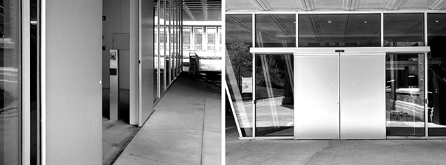
Figure 9.14. The automated motion-sensing entry door to Milstein Hall is adjacent to, and parallel to, a circulation path connecting University Avenue, seen in the background, with the Arts Quad (left). The door opens, as it did when I took the video from which the left image was obtained, whether or not the person triggering the motion sensor has any intention of entering the building, leading to gratuitous heat loss or heat gain. Eventually, push buttons were wired into the vertical mullions on both sides of the door (right), and the outside motion sensor was disabled.
Notes
1 For video showing construction of thermal-bridging bollards at the edge of Milstein Hall's loading area, see Jonathan Ochshorn, "9. Stone & Soffit," Milstein Hall Construction Videos (starting at about 2:55 minutes), here.
2 "Milstein Hall's Innovative Design."
3 The conversion of 70°F to 37°C should not be confused with the "temperature" conversion of 70°F to 21°C. What we are converting here is not a temperature of 70°F, but rather a temperature differential of 70°F.
4 "As lousy as BTU/hr per square foot rules of thumb are, a typical reasonably-tight 2500' house built to IRC 2018 code levels without excessive amounts of window will usually come in around 30,000–35,000 BTU/ hr (12–14 BTU/hr per square foot) @ 0F outdoors, 70F indoors …" "Average Heating Load," Green Building Advisor, accessed May 17, 2023, here.
contact | contents | bibliography | illustration credits | ⇦ chapter 8 |