
Jonathan Ochshorn
© 2008 Jonathan Ochshorn. This is a draft version of a paper published in the Dec. 2009 Journal of Architectural Engineering, American Society of Civil Engineers. The published JAE paper is now open-access and available for free.

Euler's famous equation for critical buckling load is rather cumbersome to derive, relying as it does on solving a second order differential equation of the form:
EI(d2y / dx2) + Py = 0.
The simplified and approximate derivation proposed here is not intended to replace Euler's brilliant work, but rather is offered as a supplementary analysis that may lend some insight into the behavior of axially-loaded columns. To anticipate the results: one can get within 3% of Euler's critical buckling load for a pin-ended column of length, L, simply by dividing the mid-span moment of a uniformly-loaded simply-supported beam of the same length by its mid-span deflection. Here's why.
Buckling occurs when a second state of equilibrium becomes possible for a given load on a column; i.e., when in addition to the obvious condition (Fig. 1-a) of axial loading, we get a second possible state of equilibrium (Fig. 1-b) with a deflected, or buckled, shape.
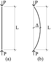
Fig. 1 Alternate states of equilibrium: (a) for straight axially-loaded column; and (b) for buckled column.
The basis for this second possible state of equilibrium is that the resisting moments in the deflected column are consistent with the moments caused by the axial load in relation to the deflected shape. One way of looking at this is to imagine that the column is first pulled into a deflected shape by some supernatural power (or just by our powers of imagination: see Fig. 2).

Fig. 2 Column pulled into a deflected position (with apologies to Michelangelo).
The column, having been stretched and compressed elastically, would attempt to regain (spring back to) its initial undeflected shape were it not for our ability to temporarily hold it in its deflected position. Now, if we quickly replace our own "supernatural" force with an axial force on the column, but leave the deflected shape as it was, we generate a bending moment due to the misalignment of the applied axial force with the internal axial forces (Fig. 3). If this moment due to the axial force is smaller than the moment caused by our initial (supernatural or imaginary) misalignment — smaller because the axial load, P, is not big enough to match the resisting moment — equilibrium cannot be maintained and the column will spring back elastically to its original (straight) position. However, if the moments caused by the applied axial load are consistent with those moments originally applied by the prior (supernatural) loading, then equilibrium is maintained, and the column can be said to have buckled.
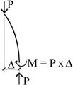
Fig. 3 Moment caused by deflection of axially-loaded column.
The axial load, P, that establishes this equilibrium is the critical buckling load, since any small misalignment will move the column inexorably from the ideal axial condition (Fig. 1-A) to the buckled state (Fig. 1-B). Based on the approximate method outlined here (as well as Euler's), this load is consistent with any deflection, so that the safety of such a column would be immediately threatened when that load is approached.
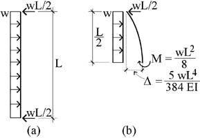
Fig. 4 Column uniformly loaded: (a) like a simply-supported beam; and (b) free-body diagram of column cut at mid-span.
To calculate the critical buckling load, Pcr, the axial load, P, is replaced with a uniformly-distributed load, w, acting along the column's length as if it were a vertical beam (Fig. 4-a). Under this loading, the mid-span moment and deflection are as follows (Fig. 4-b):*
![]()
This deflected shape is then held in place while the uniformly-distributed load, w, is removed and "quickly" replaced with an axial load, P, just big enough to maintain the mid-span deflection that we had under uniformly-distributed loading. Now, if we approximate the critical buckling load by assuming that the shape of the buckled column under axial loading is the same shape taken by the "beam" under transverse uniform loading — defined by a fourth-degree polynomial or quartic equation — we get a value that is extremely close to the Euler buckling load (within 1/10 of 1%). However, this method,** while approximate, is not particularly easy.
Instead, our approximate method uses the well-known mid-span moment and deflection values for a uniformly-loaded, simply-supported beam to compute the critical buckling load of the column. It should be noted that such an approximation presumes a critical load, moment, and deflection for which no curved shape exists. In other words, there is no curve whose strain energy of bending is consistent with the work done by a critical buckling load whose magnitude is less than the value determined by Euler. As Timoshenko and Gere point out in their Theory of Elastic Stability, any curve used to approximate the critical buckling load must result in a value greater than the value determined when the sine curve of the actual buckled shape is used. Looked at another way, if Euler's critical buckling load causes a mid-height deflection equal to that of the column viewed as a simply-supported beam with a uniform (transverse) load, w, its mid-height moment would be somewhat greater than that associated with the uniform load, w. This can be seen (Fig. 5) by examining the rotational equilibrium of a free-body diagram on which Euler's critical load buckles a column with the uniformly-loaded beam's mid-span deflection of 5wL4 / (384EI). Solving for the moment, we get M = P x Δ = wL2 / 7.78, a value slightly larger than the beam's moment under uniform load, wL2 / 8. Reducing this "buckling moment" below the value that triggers buckling — as is the case for our approximate method — means that buckling cannot actually occur and therefore no approximate curve can be found consistent with internal strain energy and external work.
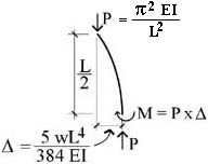
Fig. 5 Free-body diagram for buckled column.
That being said, we can still find the approximate buckling load corresponding to these "beam" values, even if no compatible deflected shape can be found. As before, rotational equilibrium for the critical buckling load (Fig. 3) is defined by Pcr = M / Δ.
Substituting the familiar "beam" values for M and Δ (Fig. 4-b) into this equation, we get:
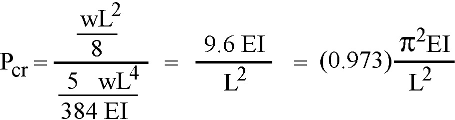
This is quite close (and slightly conservative) compared to Euler's equation:
![]()
Because all applied loads have cancelled out of these equations, the deflection associated with Pcr is indeterminate: in other words, since any deflection is consistent with this critical buckling load, the safety of such a column is fatally compromised once this load is reached.
It should be noted that even Euler's famous equation is not exact. His exact equation for buckling, rarely used in practice, shows that a point of catastrophic and sudden buckling never actually occurs.*** Rather, equilibrium may be maintained with increasing loads corresponding to increasing deflections (beyond the critical buckling load of the approximate equation), up until the point where the material's ultimate strength is exceeded and failure occurs under combined axial and bending stresses. However, deflections do increase quite rapidly once the approximate critical buckling load is reached, so that these approximate equations serve as an entirely rational indicators of the "point of no return" for the initiation of buckling.
* The mid-span moment can be found by examining the rotational equilibrium of the free-body diagram shown in Fig. 5. The derivation of the deflection equation for a uniformly-loaded, simply-supported beam is somewhat more complex, but still easier than for a buckled column. The general strategy, worked out in detail in Timoshenko, Strength of Materials, Part I, Van Nostrand Reinhold Co., New York, 1958, pp. 140-141, starts with the basic moment-deflection (y-axis) relationship, i.e., EI d2y/dx2 = -M; and the basic moment-distance (x-axis) relationship, i.e., M = (wLx - wx2)/2. Substituting the latter value for M into the first equation, and integrating twice (with the constants of integration found based on our knowledge of mid-span slope being zero and deflection at the supports being zero), we can find the deflection, y, at mid-span.
** The so-called "energy method" involves equating the strain energy of bending to the work done by the axial load as it moves vertically through a distance resulting from the curved (buckled) shape of the column.
*** For a discussion of Euler's elastica, the deflected shape of an axially-loaded column based on exact differential equations, see Timoshenko and Gere, Theory of Elastic Stability, McGraw-Hill, New York, 1961.
First posted 29 February 2008. Last updated: 18 February 2026 (open-access link)