

In general, the addition employs conventional wood framing (2x6 studs; 2x10 joists; etc.). Nevertheless, I have developed several technical innovations for this project: some make construction possible for a single worker (i.e., me) without much construction experience; some minimize costs by combining materials in unusual ways; and some improve the environmental or structural performance of the various systems.
Roof ventilation. Flat roofs are not easily ventilated, since the movement of air under the roof membrane benefits from a height differential of approximately three feet in order to drive the convection process (this "three feet" height difference requirement appears, for example, in the International Building Code where ventilators are used in conjunction with eave or cornice vents). My innovative ventilation scheme consists primarily of two elements. First, I designed a continuous plenum under the roof deck and above the insulated 2x10 "floor" structure. This plenum is connected to a continuous soffit vent below the scupper and gutter on the west side of the deck. Second, I connected this horizontal plenum to a continuous vertical plenum integrated into the parapet walls and leading to three "attic" vents visible at the top of the north and south elevations. The continuous path from soffit to attic vents triggers the necessary convective movement of air through the roof structure. This, in turn, has two important consequences: in summer, the roof membrane is kept cool, prolonging its expected lifespan, and minimizing heating loads on the upper floor of the addition; in winter, the vented space prevents the formation of both ice dams and internal condensation by providing a cold, vented space directly under the roof membrane. As a follow-up, about two years after completion, we noticed wasps nesting in the space below the roof deck planks. To prevent this from continuing, we installed hardware cloth (galvanized steel screening) in the gaps between the deck boards. See YouTube video.
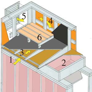
Diagram of roof ventilation: air enters at soffit vent (1), passes over insulated joists (2) through horizontal plenum (3) into parapet wall (4), and exits through attic vents (5). Roof deck (6) covers membrane roof.
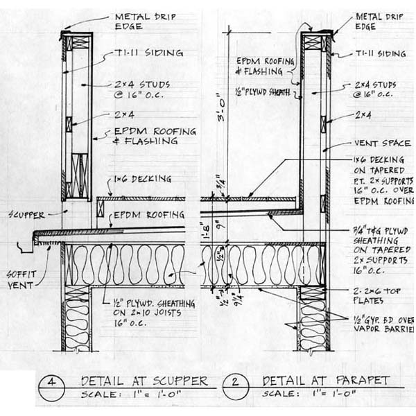
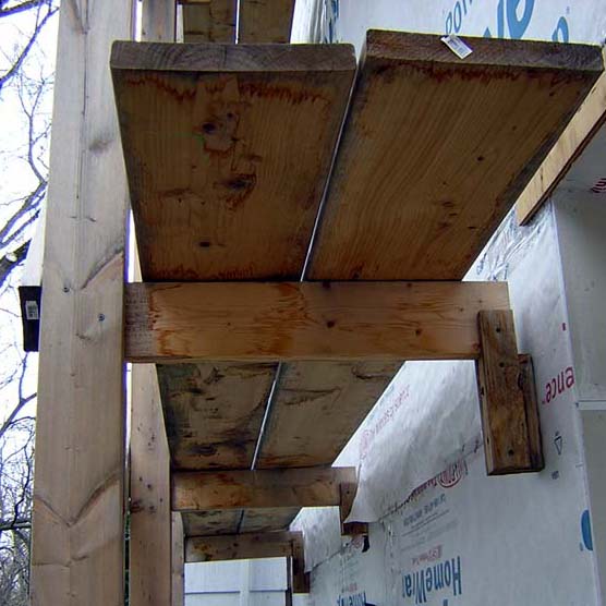
Detail section from working drawings shows layering of roof to accommodate insulation, ventilation, sloping roof membrane, and roof deck.
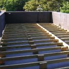
2x10 joists span between walls
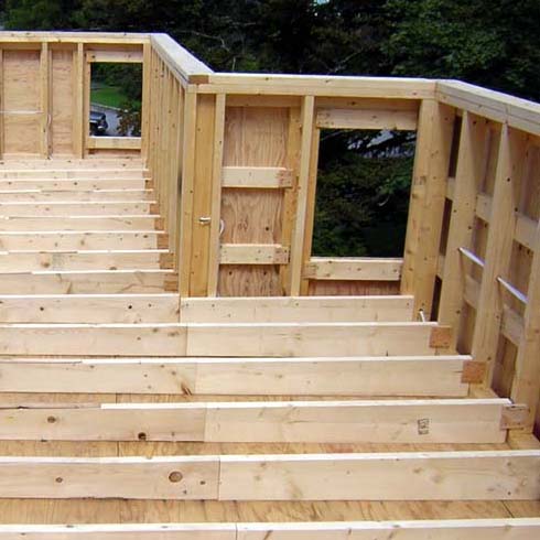
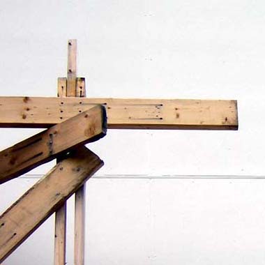
Sloped "rafters" provide vent space under membrane roofing
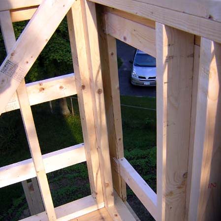
Air moves through plenum in parapet wall to opening for attic vent
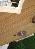
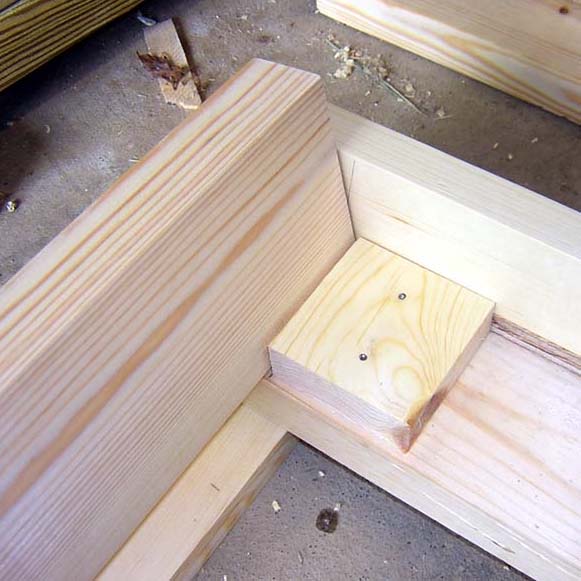
Pressure-treated 2x4s rest on roof membrane to support deck
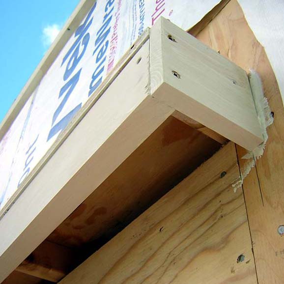
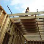
Air enters below scupper through soffit vents, shown before vents are installed
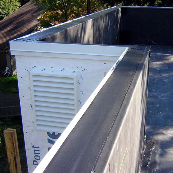
Air exits through attic vents in parapet wall
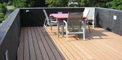
Finished roof deck is screwed into pressure-treated 2x4s below
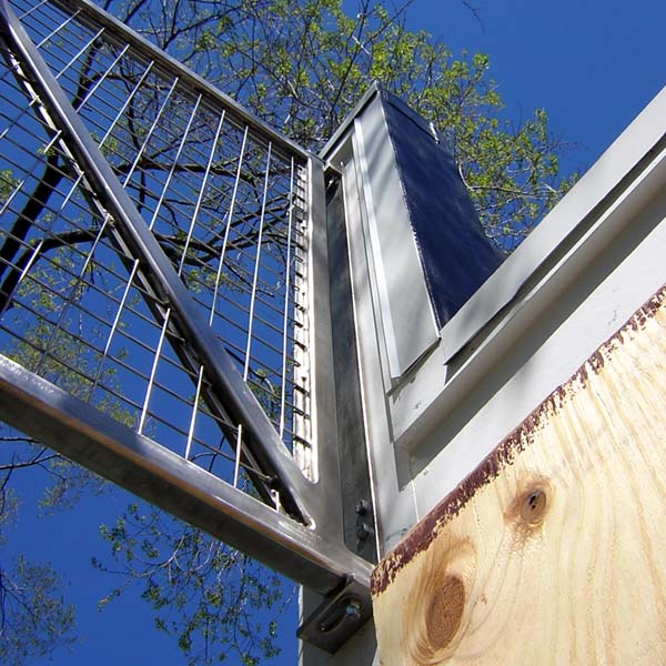
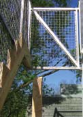
Exterior stair. In order to minimize the costs of an exterior stair connecting the mezzanine to the roof deck, I designed and engineered the stair structure in two materials: steel is used only where needed for strength, as a welded truss consisting of 1-1/2" square tubular members that supports the stair's outside wooden stringer, while simultaneously serving as a guard and handrail. The actual stair stringers and treads are fabricated from standard pressure-treated wood 2x12s, supported equally by the wooden studs of the house (on the inside) and the steel truss (on the outside). The truss geometry is carefully worked out so that the top chord can be used as the stair handrail; in general, the truss design also minimizes the weight of the steel used, so that it can be installed by workers lifting it into place from the existing scaffolding. In order to allow for thermal movement and tolerances, the upper end of the truss is supported on a specially-designed steel bracket attached to the house which allows for horizontal movement at the connection. The lower end of the truss is fastened directly into the house with 6"-long lag screws.
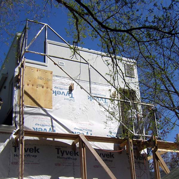
Stair truss is lifted into place and fastened through siding into stud wall
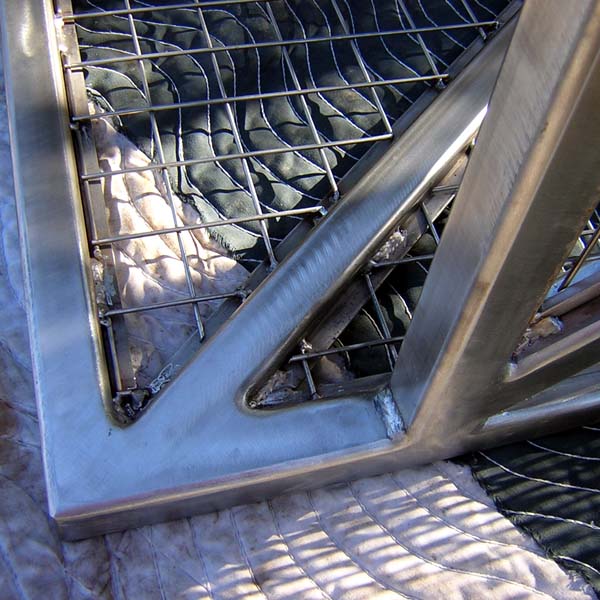
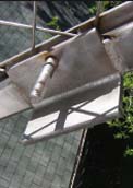
Detail of welded connections before being installed
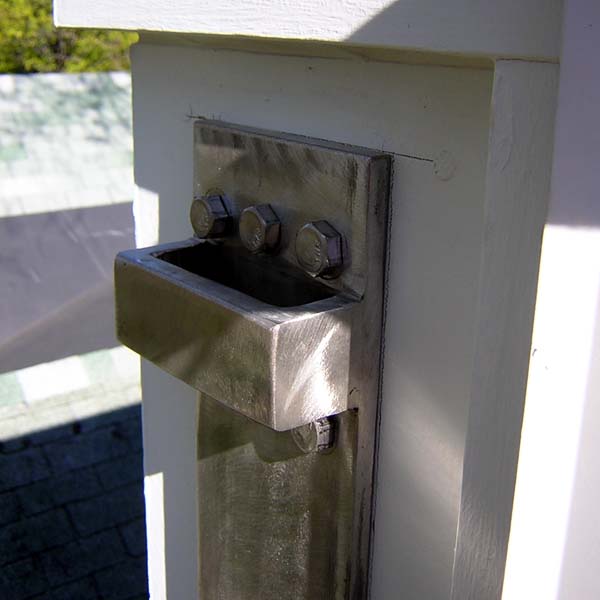
Top bracket is installed first
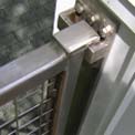
Stair truss inserted into top bracket (detail)
Stair truss inserted into top bracket
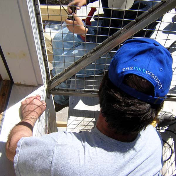
Plate at bottom of truss is fastened to wall with 6" lag screws
Clip angle is welded to bottom truss chord
Wooden stringer is fastened to clip angle
View of wooden stringer
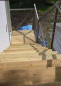
Wooden treads and landings are screwed into stringers
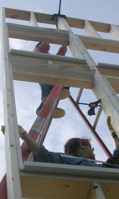
Scaffold design. In order to fasten sheathing and siding panels to the stud walls, as well as to paint the finished exterior surfaces, it was necessary to construct extensive scaffolding on all four sides of the addition. I designed a unique scaffolding system that was easy to fabricate, erect, extend higher, demolish, and reuse. The scaffolding structure consists of four elements: brackets fastened through the sheathing into 2x6 wall studs with lag screws; vertical columns made from spaced 2x6 studs (generally using those rejected from wall construction because of various defects); horizontal beams connecting the brackets and columns; and 2x12 planks spanning about six feet between scaffold beams, providing the working surface. These 2x12 planks are then reused as interior stair treads once the scaffolding is no longer needed. Because the scaffolding is fastened to the addition, it is remarkably stable. The spaced column design allows the horizontal beams to be inserted at any height, leveled, and then screwed in place; because of this, it is not necessary for each column to have the same relative height, which simplifies construction on uneven grade.
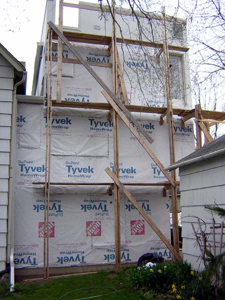
Scaffolding on south elevation
Basic elements of scaffolding can be seen here
Top of spaced column detailed to allow for vertical extension
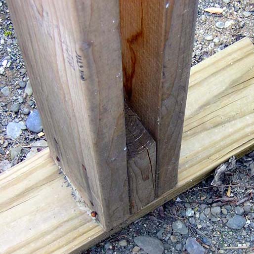
Base of spaced column nailed into pressure-treated board
Top-down construction. The scaffolding is built higher as each successive floor is constructed; i.e., new brackets are fastened to the top of the plywood sheathing that has just been completed, new spaced columns are fastened to the tops of the existing spaced columns, new beams are inserted between brackets and columns, and new (or reused) 2x12 planks are placed above the beams. In this way, plywood sheathing can be fastened from new scaffolding as the structure gets higher and higher. However, because the scaffolding is attached through the sheathing into the studs of the addition, it is not possible to leave the scaffolding in place while the siding is installed.
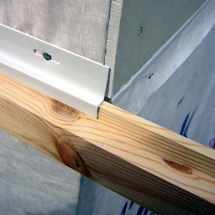
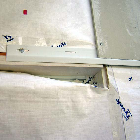
Temporary wooden spacer is inserted below z-bar flashing, helping to support siding panel to be installed above
Normally, one would start the siding (or shingles) from the bottom and work up, since the upper pieces are designed to overlap the lower ones in order to provide a water-shedding profile. Even with vertical siding panels (such as the Hardipanel cement-board siding I am using), it is usual to place z-shaped flashing along the top surface of the panels before installing the panel above, so that water cannot enter through this horizontal joint. Since this method is not possible with a scaffolding system that is fastened into the building itself, I designed a construction method that would allow for top-down installation of the siding panels. In this way, I could install the uppermost level of siding from the scaffolding, paint that level of siding from the scaffolding, and then remove the top level of scaffolding in order to begin the same process for the siding immediately below. To do this, it was only necessary to install the z-bar flashing at the bottom, rather than the top, of the siding panels. The next row of panels is then inserted up into the flashing. Aside from the advantage of being able to use the scaffolding both going up (for the sheathing and Tyvek air barrier) and then coming down (for the siding and painting), this method also protects the building from water intrusion as the siding is being installed.
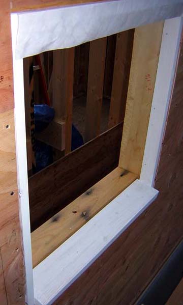
Window frame in sheathed wall
Window frame, in stud wall, being lifted into place
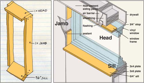
Window design. Conventional windows for new construction have an integral nailing flange that allows the window to be nailed directly into the sheathing surrounding the window opening. From my point of view, there were four problems with this: 1) the windows would all need to be installed before the exterior siding was in place, since the siding covers the nailing flange; 2) the windows would all need to be installed from the exterior side, that is, from the scaffolding, which might be difficult in some cases; 3) the glazing in such windows is actually outside the plane of the the siding, offering no protection against wind-driven rain; and 4) such windows typically come only in certain sizes, so that I would need to alter my "ideal" dimensions to suit the manufacturer's standards. To overcome these difficulties, I designed and detailed the windows as "replacement" rather than "new construction" windows. Replacement windows are manufactured to replace existing windows where the rough opening and frame are already in place. Because of this, they actually address and solve all four of the problems listed above: 1) they can be installed at any point in the construction process once the framing is complete, giving me great flexibility; 2) they can be installed from the inside, making it much easier for me to put them in place alone; 3) they can be set inside a frame, providing some protection against wind-driven rain (and simultaneously articulating the openings to a greater extent); and 4) because they are manufactured to replace existing windows, they can be ordered for any desired size. In order to use replacement windows, however, it was necessary for me to construct 26 window frames. I designed and built a special jig to set the sill angle consistently, used ordinary #2 boards (1x for the head and jambs; 5/4 for the sills), and fastened the frames into the 2x6 exterior walls while they were still being fabricated on the horizontal platform. In this way, they could be lifted into place with the walls. To make the windows as watertight as possible, the frames were detailed as follows: the heads were aligned with the face of the Hardipanel siding boards, so that the horizontal z-bar flashing for the panels could extend directly over the window heads; while the jambs were set 1/8" behind the face of the plywood sheathing, so that the Hardipanels would extend over the jambs, leaving an 1/8" space for a sealant joint.
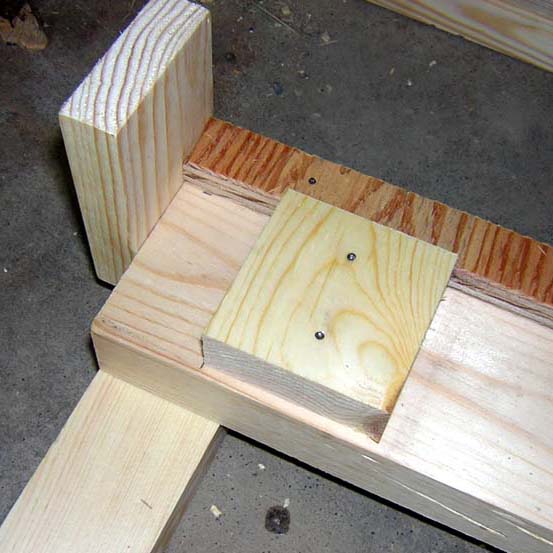
Special-purpose jig for frames
Frame being assembled in jig
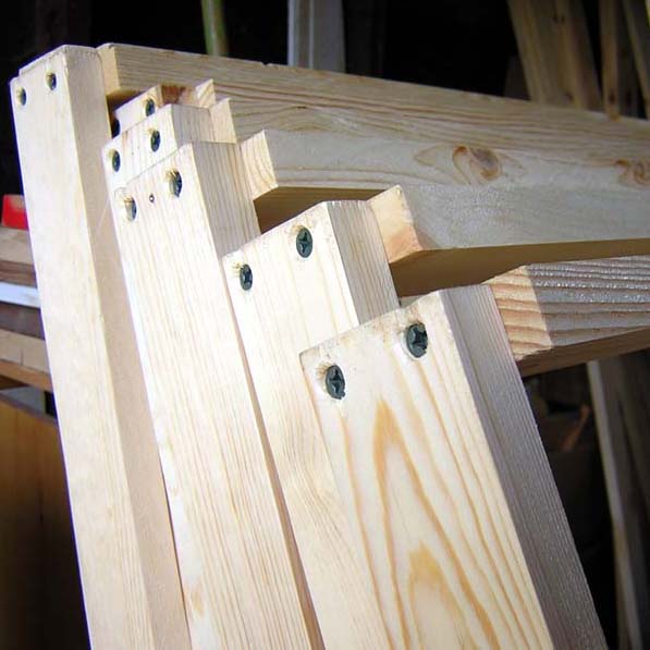
Frames before installation
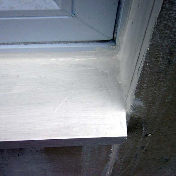
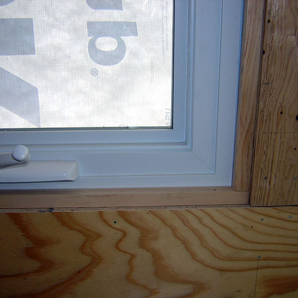
Window sill
Continuous flashing at window head
Detail of window in plywood stair hall
Window air conditioner adapted to through-wall design. We used standard window a/c units but adapted them so that they could be used in the wall (where they can be left year-round) rather than in the window, which would be awkward with casement windows. To do this, we basically created a "fake" window opening, similar to the type shown above, but with a moveable 2x6 that simulates the behavior of an ordinary double-hung window top sash. This video explains the process, and also shows how we made an insulated removable picture frame to help prevent winter drafts through the opening.
Foundation relief. Typically, one would support a house addition on the side of the house to which it is attached. In this case, I was concerned that the existing concrete block house foundation wall adjacent to the proposed addition was already distressed (bowed) under existing loads, and might not be able to handle additional stress. Since I wanted to avoid any intervention with the existing overhanging roof of the house, I developed a strategy of building the addition essentially as a free-standing structure on a rectangular foundation wall separated from the existing house by three feet. I then designed a connection between the two structures at the foundation level so that new reinforced concrete connecting walls would actually brace the unstable concrete block walls of the existing house. It was then possible to insert a 3-foot wide roof structure under the existing overhanging roof, and place appropriate program elements within the zone thus formed (stair, closets, bathroom). I developed and built an innovative insulation system within the formwork to allow for continuity of the foundation insulation at the two junctures of the basic rectangular foundation walls with the 3-foot connecting walls.
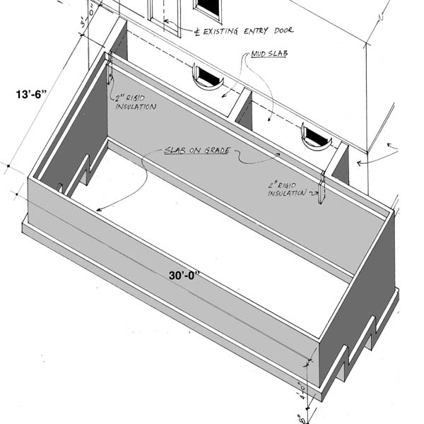
Axonometric of foundation system
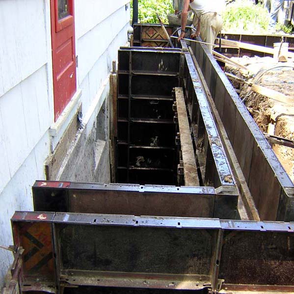
Connection at existing house
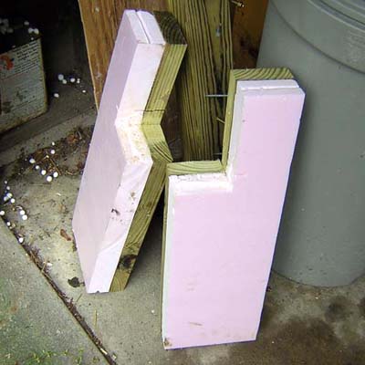
Insulation inserts
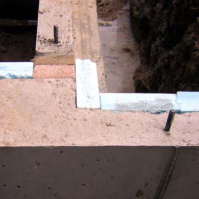
Insulation inserts installed
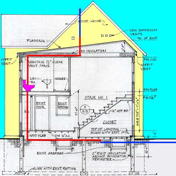
Connections (shown in red) are made to existing vent in attic and existing waste line near basement ceiling (shown in blue)
Plumbing integration. The existing house has an unusually high waste pipe, almost at the ceiling of the existing basement. This made the design of a new bathroom and utility sink more interesting that would otherwise be the case. It was necessary to consider how the new plumbing pipes would connect with the existing system, especially since the new stair in the zone between the addition and existing house made it impossible to reach the vertical waste pipe servicing the existing bathrooms. The solution took advantage of a 1-foot height differential between the existing and new first floor elevations. It was possible to run the waste pipe from the new bathroom through the horizontal plenum created by the 1-foot differential, and connect it directly to the existing cast iron waste pipe in the existing basement. In a similar manner, it was possible to run the new plumbing vent through the "attic" of the the 3-foot wide connecting zone and then to join the existing waste pipe where it penetrates through the existing attic. In this way, no new roof penetrations were required.
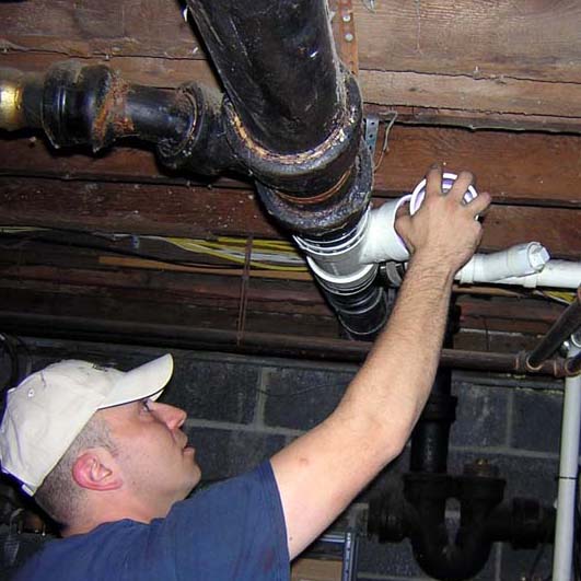
Connection made to existing waste line in basement
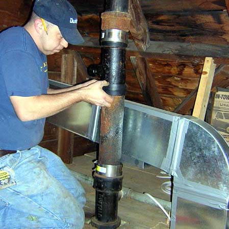
Connection made to existing vent in attic
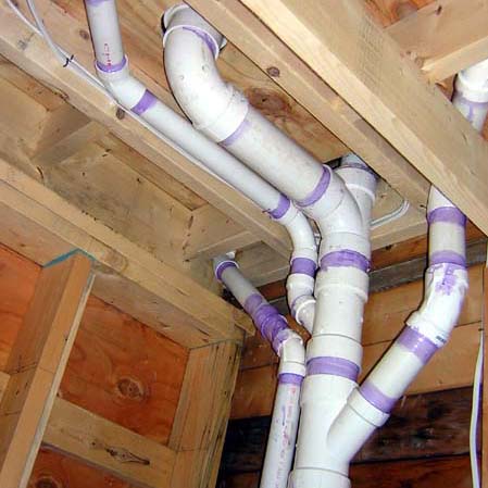
Waste pipes in plumbing chase (behind closet)
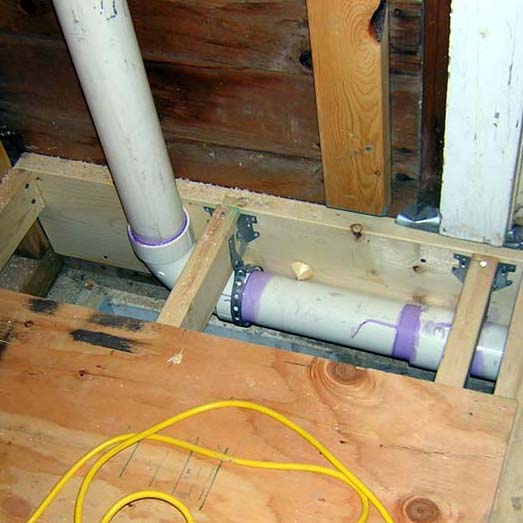
Waste pipe continues under new stair landing
Rainwater harvesting. After the addition was completed, I recycled five 50-gallon food-grade barrels in order to harvest rainwater from the roof of the addition and original house.
last updated: 23 June 2024
Copyright 2005-2011 J. Ochshorn. All rights reserved. Republishing material on this web site, whether in print or on another web site, in whole or in part, is not permitted without advance permission of the author.