ARCH 2615-5615 Building Technology II: Structural Elements
Spring 2022
Jonathan Ochshorn
Assignment #6: Reinforced concrete structural design
Issued April 14, 2022
Due: April 19, 2022, 9:40 AM* (upload PDF to canvas)
Solutions
For the reinforced concrete girders, beams, and 1-way slabs described below and illustrated in Fig. 1, assume the following:
- Retail (upper floor) occupancy with L = 75 psf. Do not consider live load reduction and do not enable "bundled bars."
- Dead load (for T-beams) = weight of reinforced concrete, taken at 150 pcf. There is no additional dead load.
- Assume a centerline span for the T-beam of 31 feet. Assume that the number of "girder divisions" is 5, so that the centerline span of the girder is 5 x the beam centerline spacing (see cross section for spacing dimensions). Assume a girder stem width of 24 inches.
- Assume moment values of wuL2/11 for negative moment and wuL2/16 for positive moment for beams, girders, and slabs.
- Use f'c = 4,000 psi (4 ksi) for concrete and fy = 60,000 psi (60 ksi) for steel rebars.
- Use 3 inches cover for beams and girders, and 1 inch cover for slabs (where "cover" in this context is measured to the centerline of the rebars).
- Assume a maximum aggregate size of 1 inch.
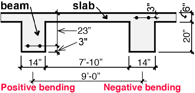
Figure 1. Cross section through typical T-beams and slab. Slab reinforcement and stirrups in beams are not shown. These T-beams frame into girders, also not shown. And the girders frame into columns, also not shown. The whole system of columns, girders, beams, and slabs is schematically illustrated in Fig. 2 below.
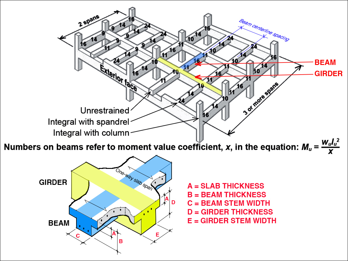
Figure 2. Schematic representation of column/girder/beam/slab hierarchy, adapted from the text for the reinforced concrete beam/girder/slab calculator.
Requirements
A. Use online reinforced concrete beam/girder/slab calculator to design the followings:
- Find steel bar size choices for (a) negative-moment beam (T-beam) and (b) positive moment beam (T-beam).
- With a girder stem width of 24 inches, find the smallest girder thickness that works for both negative and positive moment (use only even integers like 32", 34", 36", etc.).
- Find spacing and bar size for (a) negative-moment slab and (b) positive moment slab.
- Take 2 screen shots, one for the values you input (top of calculator) and the other for the answers (bottom of calculator). These two screen shots will include all the information for the beam, the girder, and the slab design. Embed the screen shots in your pdf.
B. Use online reinforced concrete stirrup spacing calculator to design the followings:
- Find distribution of No. 3 stirrups in T-beam.
- To find the design shear at the support of the T-beam, Vu, use the distributed load, wu, as explained below.
- Take 1 screen shot including both values input and calculated answers. Embed the screen shot in your pdf.
C. Use online reinforced concrete column calculator to design a column with the following specifications:
- Find bar size for a 14" x 14" tied column supporting a design load of 530 kips, using 4 bars — one at each corner. This calculation does not have anything to do with the T-beam design parameters, except that it assumes the same concrete and steel specifications, i.e., f'c = 4 ksi for concrete and fy = 60 ksi for steel rebars. The column dimensions are also compatible with the beam and girder stem widths specified above, although this is not an absolute requirement — the column dimensions can be smaller or larger than the beam and girder stem widths.
- Select "Method B" for the "design of column with dimensions assumed."
- Take 1 screen shot of the "Method B" portion of the calculator including both values input and calculated answers. Embed the screen shots in your pdf.
Upload a single pdf with all your screen shots using the Canvas interface.
Some help...
To find the distributed load, wu, on the T-beam, compute the dead and live loads and then find the "design" load which is equal to 1.2D + 1.6L.
The dead load = 150 x {(9 x 6/12) + (14/12 x 20/12)} = 966.67 #/ft
The live load = 75 x (9 x 1) = 675 #/ft.
The total uniformly distributed design load wu = 1.2D + 1.6L = 1.2(966.67) + 1.6(675) = 2240 #/ft = 2.24 k/ft.
This value of wu is used to find the "moment values" for negative and positive bending, and also the maximum design shear force for the stirrup spacing calculator. To find the maximum design shear force, Vu, just assume a simply-supported clear span of 31 – 2 = 29 feet, and compute the maximum shear by dividing the total design load (wu × clear span) by two. See Example 5.8 in the text for a sample calculation of maximum shear force (Figure 5.41).
* Note that the grace period for late assignments ends at 9:40 AM on Thursday, April 21, 2022. Assignments will not be accepted after that point.
© 2021 Jonathan Ochshorn. First posted 4 April 2021. Last updated: 20 February 2022
ARCH 2615-5615 Building Technology II: Structural Elements
Spring 2022
Jonathan Ochshorn
Assignment #6: Reinforced concrete structural design
Issued April 14, 2022
Due: April 19, 2022, 9:40 AM* (upload PDF to canvas)
Solutions
For the reinforced concrete girders, beams, and 1-way slabs described below and illustrated in Fig. 1, assume the following:
Figure 1. Cross section through typical T-beams and slab. Slab reinforcement and stirrups in beams are not shown. These T-beams frame into girders, also not shown. And the girders frame into columns, also not shown. The whole system of columns, girders, beams, and slabs is schematically illustrated in Fig. 2 below.
Figure 2. Schematic representation of column/girder/beam/slab hierarchy, adapted from the text for the reinforced concrete beam/girder/slab calculator.
Requirements
A. Use online reinforced concrete beam/girder/slab calculator to design the followings:
B. Use online reinforced concrete stirrup spacing calculator to design the followings:
C. Use online reinforced concrete column calculator to design a column with the following specifications:
Upload a single pdf with all your screen shots using the Canvas interface.
Some help...
To find the distributed load, wu, on the T-beam, compute the dead and live loads and then find the "design" load which is equal to 1.2D + 1.6L.
The dead load = 150 x {(9 x 6/12) + (14/12 x 20/12)} = 966.67 #/ft
The live load = 75 x (9 x 1) = 675 #/ft.
The total uniformly distributed design load wu = 1.2D + 1.6L = 1.2(966.67) + 1.6(675) = 2240 #/ft = 2.24 k/ft.
This value of wu is used to find the "moment values" for negative and positive bending, and also the maximum design shear force for the stirrup spacing calculator. To find the maximum design shear force, Vu, just assume a simply-supported clear span of 31 – 2 = 29 feet, and compute the maximum shear by dividing the total design load (wu × clear span) by two. See Example 5.8 in the text for a sample calculation of maximum shear force (Figure 5.41).
* Note that the grace period for late assignments ends at 9:40 AM on Thursday, April 21, 2022. Assignments will not be accepted after that point.
© 2021 Jonathan Ochshorn. First posted 4 April 2021. Last updated: 20 February 2022