Fall 2020
Jonathan Ochshorn
Issued Oct. 19, 2020
Due Oct. 26, 2020, 3:00 pm (upload PDF to canvas)
Modern buildings increasingly are constructed based on the concept of control layers: air barriers, thermal control layers (insulation), rain water control layers, and vapor control layers, all protected by some sort of cladding. In many cases, the rain water, air, and vapor control layers consist of a single membrane applied over sheathing, followed by insulation, and air space, and then the cladding.
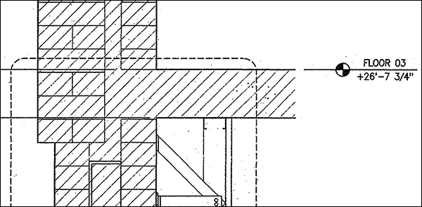
Draw the section at 1-1/2" = 1'-0" or, if using metric scales, at 1:10. No dimensions are required, but show and mark an elevation corresponding to the top of floor, as in the edited MilsteinHall detail shown immediately below. (Just make up any elevation height!)
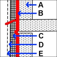
From the lecture notes: "The key diagram is reproduced below, with additional annotations as follows: A = the structure and back-up wall structure (notice the space between the top of the back-up wall and the structural slab to allow for movement); B = the air barrier (notice the allowance for movement where the air barrier spans the "void" at the intersection of wall and slab) including flashing to drain the cavity; C = insulation tight against the air barrier; D = a drainage cavity (or pressure-equalization chamber if detailed rigorously); E = the rainscreen/sunscreen."
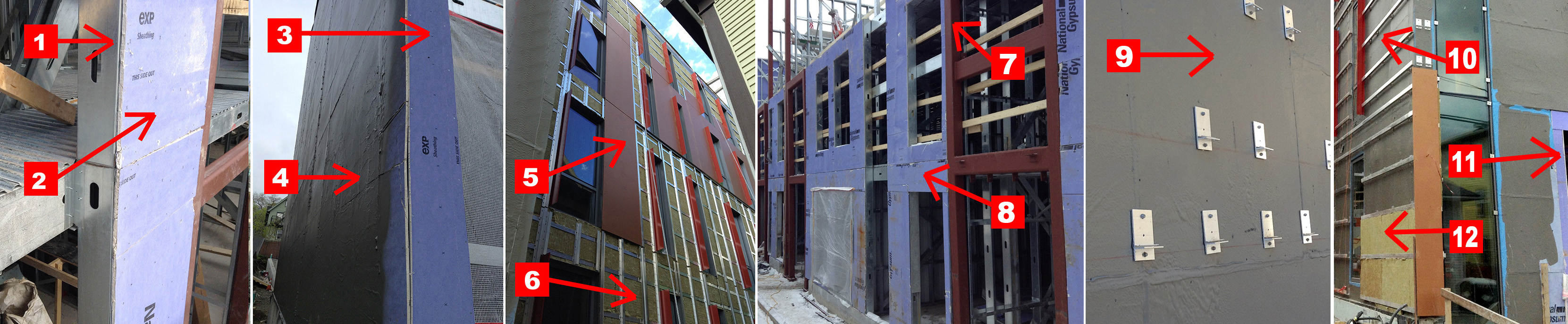
In the case study building (College Townhouses on College Avenue in Ithaca, NY), an air-water-vapor barrier is applied over sheathing boards which are fastened directly to structural steel studs. So, the "structure and back-up wall" labeled "A" in the diagram above corresponds to structural steel studs and sheathing boards in the case-study building. In other words, there really isn't any "back-up wall" in the case study building (since the steel studs are the actual structure), so a space for movement between structure and back-up wall (shown in the diagram) isn't necessary in this case.
Format the assignment on any size sheet listed in the NCS, with a border and title block following the NCS guidelines.
Copyright
2019–2020 J. Ochshorn. All rights reserved. First posted: 7 Oct. 2019 | last updated: 24 October 2020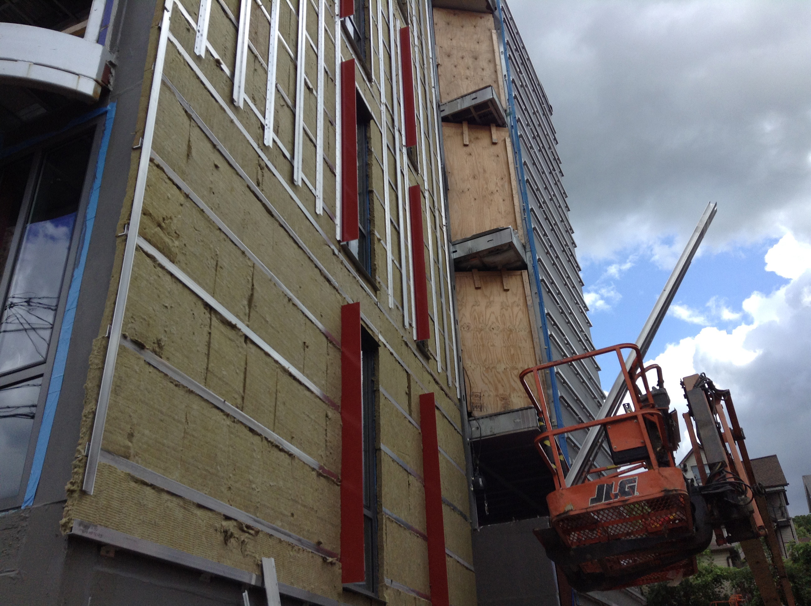