contact | contents | bibliography | illustration credits | ⇦ chapter 6 |
7. BUILDING GOOD: STRATEGIES, OBSTACLES, FICTIONS
Understanding how buildings function and adapt to changing conditions is not self-evident. Clients don't always know what they want, the future is always uncertain, and what appears as an appropriate response may bring unanticipated negative consequences.
Strategies
In order to "build good," i.e., to avoid creating dysfunctional or inflexible buildings in this baffling context, two seemingly contradictory strategies are available to designers. On the one hand, designers can carefully examine and, where appropriate, reproduce traditional building elements that seem to work. At best, such building elements, having evolved over long periods of time, solve problems without creating new ones—even if their multi-dimensional functionality is not fully understood by the designer. Ignoring such traditional wisdom may result in dysfunctional solutions since the multiplicity of functions, often combined and therefore hidden within traditional designs, may not be recognized as such or, even worse, may be discarded out of contempt for what is seen as being merely prosaic and functional.
On the other hand, designers must understand and account for changes in social behaviors, building science, and building materials, since strategies that might have been appropriate in the past (i.e., precisely the traditional or vernacular logic that was just cited) may be incompatible with modern practice. Ideally, what remains relevant in traditional practice is integrated into contemporary building theory, so that one can safely discard the ideological baggage of the vernacular without completely losing its wisdom.
It would be nice if there were a few concise bullet points to encapsulate the essential elements of good building, analogous to Michael Pollen's advice for healthy eating ("Eat food. Not too much. Mostly plants.").1 Joseph Lstiburek makes an attempt with his advice for sustainable building ("Use lots of insulation, airtight construction, controlled ventilation, and not a lot of glass"),2 but his four prerequisites for low-energy construction—while important—address only one aspect of good building, out of hundreds or even thousands of building issues. In fact, there simply is no way to cover all the specific elements of good building in a few bullet points; Christopher Alexander, for example, identified 253 patterns and took over one thousand pages of text to explicate his system of interrelated building problems and solutions.3 Still, it may be possible to offer the following general principles for building good:
- Pay attention to what has worked in the past, unless contradicted by current building science and social conventions.
- Prioritize health, safety, and welfare.
- Refuse to compete on the basis of defamiliarized form, dysfunctional features, or diagrammatic fictions.
Obstacles
While these strategies for building good might prove useful within some small corners of architectural culture, none of this advice is relevant to designers pursuing avant-garde notoriety. As I argued in a blog post introducing my book, Building Bad:
The question posed in the epilogue—'whether and how the art of architecture can adjust its trajectory so that it aligns with the most fundamental requirements of building science'—remains unanswered, as it must: Architecture's dysfunction, running parallel to the dysfunction of society as a whole, constitutes an essential feature of avant-garde production, not a flaw. This dysfunction is consistent with and, in fact, thrives within the ethos of human and environmental damage that undergirds modern democratic states.4
Aside from the dysfunctional competition that drives defamiliarized avant-garde design,5 the hidden multi-dimensional functionality of many traditional building elements can be problematic even for designers who eschew the pretensions of avant-garde production. The temptation to solve a problem by deviating from some normative standard is often present, since the negative ramifications of doing so may not be obvious. But such modifications may well affect a crucial aspect of an element's multi-dimensional functionality that was not recognized as such.
Fictions
In Milstein Hall, many problems with function and flexibility can be attributed to the architects' disinclination to integrate and reconcile traditional wisdom, drawn from careful study of past practices, with an evolving building science, driven by new materials and new standards for energy, carbon, and comfort. Instead, the architect's priority is to defamiliarize traditional elements in order to exploit the expressive potential of purposefully distorted or abstracted geometries based on diagrammatically clear, single function "cartoons" of solutions. In such cases, the functions not considered inevitably show up, uninvited, at the designer's or client's metaphorical door demanding ransom and exacting revenge.
The underlying diagrammatic cartoon from which much of Milstein Hall's dysfunction originates can be understood by examining a campus site plan (fig. 7.1) in which an east-west zone is delineated such that it brackets the primary buildings of the college (Tjaden, Sibley, and Rand Halls as well as the art museum to the west); while a north-south zone conceptually ties the college's Foundry structure, north of University Avenue, to the eastern buildings of the Arts Quad along Feeney Way (formerly East Avenue).
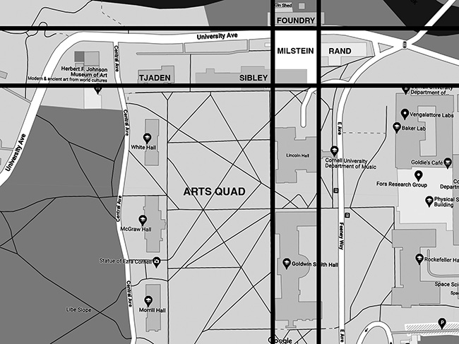
Figure 7.1. I've interpreted the diagrammatic basis for Milstein Hall's siting on this campus plan: an east-west zone brackets the primary buildings of the college (Tjaden, Sibley, and Rand Halls as well as the art museum to the west); while a north-south zone conceptually ties the college's Foundry structure to the eastern buildings of the Arts Quad. Milstein Hall occupies the intersection of these two zones.
Milstein Hall is then placed precisely at the intersection of these two zones, symbolically forming a linchpin or connecting structure—a "contiguous, multi-layer system of buildings and plazas" that, according to the architects, "unites the disparate elements of the AAP."6
We've already seen in chapter 5, on circulation, that merely placing Milstein Hall at a location between Sibley Hall, Rand Hall, and the Foundry is not something that, in and of itself, "unites the disparate elements of the AAP." Rather, the explanation is a conceptual fiction designed to provide plausible deniability to the charge of gratuitous defamiliarization. Or, to reiterate Thorstein Veblen's argument in his analysis of women's dress, it is just a smokescreen where "each added or altered detail strives to avoid instant condemnation by showing some ostensible purpose, at the same time that the requirement of conspicuous waste prevents the purposefulness of these innovations from becoming anything more than a somewhat transparent pretense."7
The idea of embracing fictional constructs is a recurring theme in the writings of Rem Koolhaas. In Delirious New York, he argues not only that "the Appendix should be regarded as a fictional conclusion, an interpretation of the same material, not through words, but in a series of architectural projects," but also that the book itself "describes a theoretical Manhattan, a Manhattan as conjecture, of which the present city is the compromised and imperfect realization."8 In fact, fiction for Koolhaas is not a flaw, but a feature of his presentation. Channeling Salvador Dalí's so-called paranoid-critical method, and anticipating Donald Trump, he extols fake news and speculation: "Paranoid-Critical activity is the fabrication of evidence for unprovable speculations and the subsequent grafting of this evidence on the world, so that a 'false' fact takes its unlawful place among the 'real' facts."9 In Milstein Hall, additional conceptual fictions, distortions, and half-truths—embodying Veblen's "transparent pretense"—have been promoted by the architects or their acolytes. A partial list follows:
- From OMA's website: "Milstein Hall provides a type of space currently absent from the campus: a wide-open expanse that stimulates the interaction of programs, and allows flexibility over time."10
The geometry of Milstein Hall's second-floor plate, filling up the diagrammatic space shown in figure 7.1, makes it difficult to use the building for typical classroom, office, and related functions. Only a few Cornell campus buildings have similar dimensions (fig. 7.2), and in those buildings—like Uris Hall, designed by Pritzker Laureate Gordon Bunshaft of S.O.M.—the deep floor plan leaves many offices and classrooms windowless, and creates a maze of circulation corridors making orientation difficult, even with a more rational placement of core elements like stairs, elevators, and bathrooms, in the building's center (fig. 7.3).
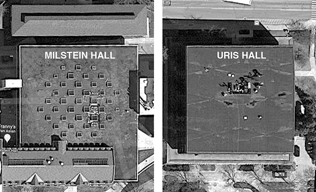
Figure 7.2. Milstein Hall (left) and Uris Hall (right) on the Cornell University campus are of similar size and shape, as can be seen in these Google Map satellite views taken at the same scale and orientation.
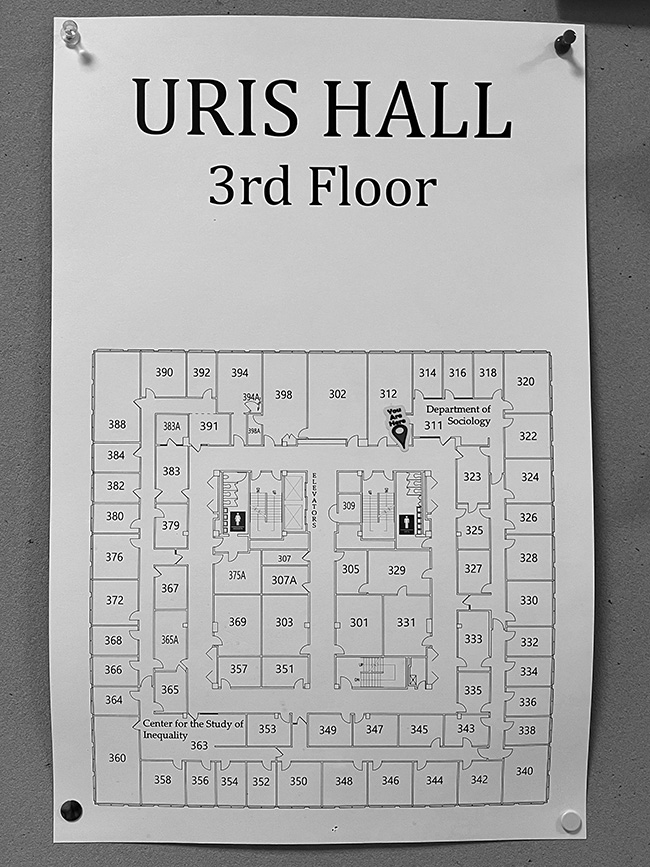
Figure 7.3. Uris Hall at Cornell University has similar dimensions as Milstein Hall, and illustrates the difficulty of placing classroom and office occupancies in such a deep floor plan without creating windowless rooms and a maze of circulation corridors.
In Milstein Hall, a large percentage of perimeter space can have no windows to the outside because of adjacencies to Sibley Hall and Rand Hall. Similarly, what were flexible office or classroom spaces on the second floor of East Sibley Hall have now become less useful and less flexible since their "windows" now look directly into Milstein Hall's studio floor and have become non-operable components of a fire barrier separating the two buildings.
- From Cornell's website: "The sustainable design goals for Milstein Hall are met through the use of good design practice to provide a healthy and comfortable environment for the building occupants."11
Having defined the building location for Milstein Hall at the intersection of conceptual east-west and north-south zones shown in figure 7.1, the architects then make the building as energy-inefficient as it is physically possible to do, wrapping the entire perimeter at all levels with "floor-to-ceiling windows," irrespective or orientation or function. More problematic, from an energy perspective, is the decision to lift the second-floor studio into the air to align with and connect to the second floors of Sibley and Rand Halls, while depressing the lower level into the ground to align with the basement of Sibley Hall (Rand Hall has no basement). Aside from a small portion of below-ground basement ceiling/roof area and upper-level soffit that is enclosed by the glazed perimeter of the auditorium and entry mezzanine, the enormous expanse of second-floor soffit and basement ceiling/roof area becomes exposed to the weather, along with the vegetated roof, punctuated by skylights, over the second-floor studios. And, as the architects note with approval, not only the auditorium but also Milstein Hall's second-floor studios are surrounded by "floor-to-ceiling windows," except where Milstein Hall's second floor connects with Sibley Hall and Rand Hall (fig. 7.4).
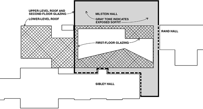
Figure 7.4. Surfaces of Milstein Hall that are exposed to the weather: The black perimeter line bounds the upper studio level, defining the roof; the gray-toned area within the black perimeter line represents the exposed second-floor soffit; the cross-hatched area represents the exposed roof of the basement, which extends under the outdoor plaza and loading area to the west of the main part of the building.
Traditional or vernacular wisdom suggests that, in Ithaca's severe climate region, architects should employ the opposite strategy for a building's massing. Rather than articulating and separating the building's constituent parts, thereby maximizing the surface-area-to-volume ratio, they should "use a compact design with a minimum surface-area-to-volume ratio."12 Yet as a result of OMA's complex form-making, Milstein Hall's volume of 723,795 cubic feet (20,496 cubic meters) corresponds to an incredibly large exposed surface area of 73,984 square feet (6,873 square meters).13 To show how these numbers compare to a hypothetical building with a more rationally configured geometry, we can take Milstein Hall's volume but organize it within a normative 3-story building with an occupiable basement (similar to many of Cornell's traditional campus buildings). Giving this hypothetical building a width of 64 feet (20 m)—the "optimal" width for a campus building proposed by Stewart Brand that was discussed earlier—and using Milstein Hall's basic floor-to-floor heights, we get, for the same volume of 723,795 cubic feet (20,496 cubic meters), a reduced total exposed surface area of 36,639 square feet (3,404 square meters). In other words, a rationally configured geometry with the same volume as in Milstein Hall would have half of Milstein Hall's exposed surface area, making it far more energy efficient. Of course, this hypothetical version of Milstein Hall would also be far more functionally efficient and flexible.
- From OMA's website: "The new Milstein Hall," according to the architects, features "a large elevated horizontal plate that links the second levels of Sibley and Rand Halls and cantilevers over University Avenue, reaching towards the Foundry building."14
The extreme cantilevers of Milstein Hall's top story—extending 48 feet (14.6 m) over University Avenue—necessitate an elaborate and material-intensive structural work-around consisting of five floor-to-ceiling-height hybrid trusses that have been distorted, at the architect's insistence, so that none of the vertical or diagonal members intersect at common nodes along the top and bottom chords, as would be the case in a true truss with predominantly axial forces. This distortion effectively destroys the structural logic of the truss by introducing enormous bending moments into all of the structural members, so that it becomes less of an efficient axial-force structure, and more of an inefficient rigid-frame structure. The convoluted logic underlying this geometry is "explained" by OMA partner-in-charge Shohei Shigematsu:
The decision to put all the studios into one single linking space meant that the building would have to cantilever far out over the road at the edge of the site, which then meant that two extra trusses had to run down inside the studios. The circulation problems created by these trusses prompted a clever hybrid solution, whereby in the less stressed middle part of the building the frame can be a vertical (or "Vierendeel") truss, while as the strains get greater towards the edges, the truss becomes more angular. "You can instantly see where the forces are going," Shigematsu says. "We thought it was interesting for the students pedagogically to see how the forces are actually in the truss."15
None of this is true. The argument starts with the premise that "all the studios" have been placed into "one single linking space." In fact, numerous architecture studios are assigned to spaces outside of Milstein Hall—some are on the third floor of East Sibley Hall, and the rest are in the college's New York City and Rome facilities. The entire justification (putting "all the studios into one … space") for this audacious cantilever is bogus. The argument continues by claiming that the distortion of the truss into a "hybrid" rigid frame is a result of "circulation problems created by these trusses." In fact, one can circulate quite easily through a normative truss, as shown in figure 7.5.
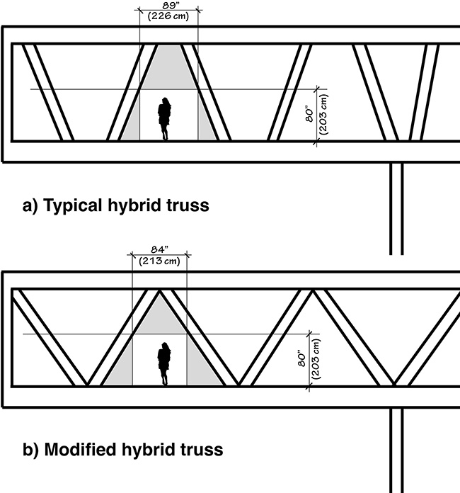
Figure 7.5. Milstein Hall's typical hybrid trusses (a) provide about 89 inches (226 cm) of space for circulation over the cantilever; a modified and more structurally efficient design (b) would provide about 84 inches (213 cm) of space—virtually the same amount.
Next comes the structural justification for the distorted truss geometry at the cantilevered section, where it is argued that "as the strains get greater towards the edges, the truss becomes more angular." But this turns the structural logic inside-out: instead of starting with the most efficient truss form—one where all diagonals and verticals intersect at nodes along the top and bottom chords—and only then making whatever modifications are deemed necessary to facilitate circulation, OMA's argument starts with the most inefficient truss form imaginable—a so-called Vierendeel truss with no diagonal members—and then modifies this grossly inefficient rigid frame by angling some of the vertical members slightly where internal forces and moments would otherwise be higher. It is a type of argument eerily similar to Milstein Hall's bogus energy cost calculation, described in chapter 22, in which a "baseline" (i.e., worst-possible) building is used as a point of comparison with the actual modeled building, so that even a terrible proposal, compared with the baseline, looks good.
As can be seen in figure 7.6, the maximum bending moment in the hybrid truss, resulting from this cascading series of bad decisions and bogus explanations, is more than three times the equivalent value in a hypothetical and slightly less illogical hybrid truss where diagonals in the cantilevered section, still rigidly connected, are made to intersect at common nodes along the top and bottom chords. And while my modified structural model and load assumptions are simplified compared to the actual structural design, the conclusions can be taken as sound.16
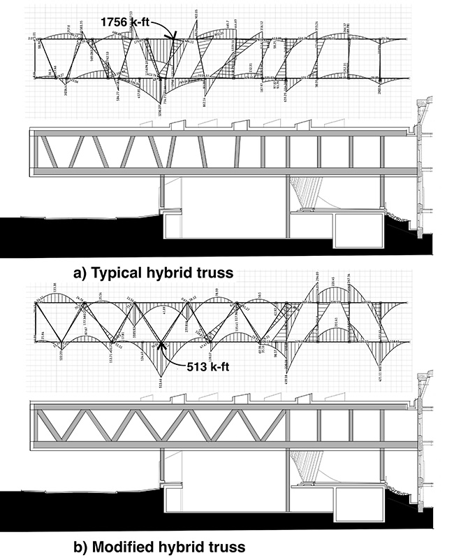
Figure 7.6. Making simplified assumptions about the structural geometry and loads, one can see that (a) Milstein Hall's "clever hybrid solution" produces bending moments that are more than three times greater than (b) a modified version with more rational deployment of diagonal members over the cantilever.
The final argument that the architects make for these hybrid trusses is that they serve as a teaching tool: "We thought it was interesting for the students pedagogically to see how the forces are actually in the truss," says OMA's Shigematsu. Cornell's website goes even further, arguing that "in its own right, the hybrid truss becomes a laboratory for teaching architects structural design concepts."17 These contentions are particularly annoying for two reasons. First, students cannot see forces, bending moments, or any other structural action, when they look at these hybrid trusses. As I have written elsewhere, "Not only is the expression of structure different from structural behavior, but the actual behavior of structural elements and systems is not at all self-evident: all structural action takes place 'beneath the surface' so that our view of structure is, literally, superficial. We do not see tension in a suspension bridge cable or compression in a stone column."18 Rather, the path to structural insight is, like all forms of creativity, a patient search: Felix Candela wrote that architects "appear to be convinced that there is no need to make any great effort—that a 'flash of genius,' a sudden inspiration, is quite enough to create a structure of novel and original conception. Unfortunately, the creative act is hardly ever the result of effortless inspiration. It is, instead, the—sometimes belated—result of long and painstaking work, the fruit of many years of constant effort and steadfast mental occupation with the problem concerned."19
The behavior of a simple truss is so sensitive to span and load conditions that even structural form-finding methods embodied in graphical statics—certainly a step above merely "seeing" the trusses—are still virtually useless as pedagogic tools for students. In my paper, "Revisiting Form and Forces," I argued that when "using graphical statics, trusses of radically different spans … end up 'finding' exactly the same form. The author's analytic optimization exercise, on the other hand, shows that the optimal aspect ratio for a truss actually increases as its span increases, revealing the limits of a graphical statics 'form-finding' approach."20
Second, it is distressing to think that students would ever be tempted to take this dysfunctional architectural form, and the structural gymnastics that enable it, as a precedent for their own design explorations. Yet characterizing Milstein Hall as a structural laboratory implies that the building might serve as a positive role model in this respect. As if…
- Shohei Shigematsu of OMA states: "Our ambition was that this was almost like a covered interior space, so we looked at typical American tin decorated ceilings, and then we just blew them up four times as big and used them as ceiling panels."21
Many of Milstein Hall's problems with function and flexibility can be attributed to the architects' disinclination to integrate and reconcile traditional wisdom, drawn from careful study of past practices, with an evolving building science, driven by new materials and new standards for energy, carbon, and comfort—except where those elements are mined for their expressive potential, as in the appropriation of traditional "American tin decorated ceilings" for the underside of the second floor (fig. 7.7).
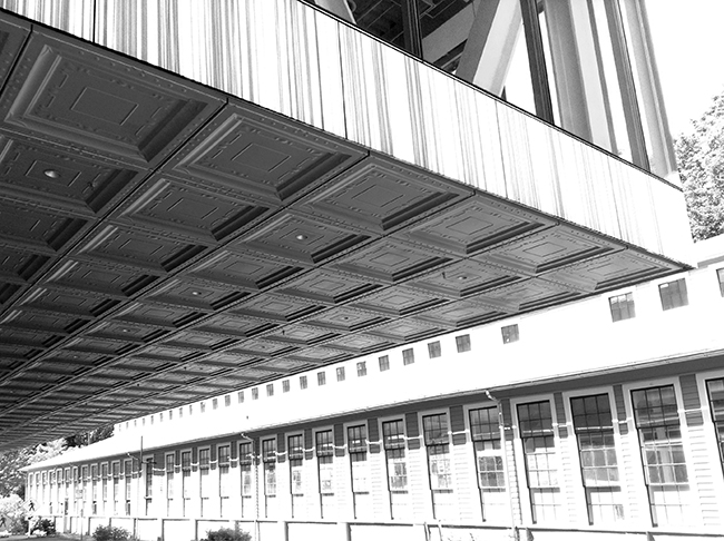
Figure 7.7. Milstein Hall's stamped aluminum soffit panels reference traditional Victorian tin ceilings. Image shows the cantilevered portion over University Avenue facing the Foundry.
Tin ceilings were invented in the U.S. in the late nineteenth century as "a more affordable and more durable option to intricate plasterwork that was popular on European ceilings in the late 1800s."22 In Milstein Hall, the ceiling/soffit panels certainly work as eye candy, but fail to take advantage of their ambiance—whether construed as nostalgic or ironic—to enliven Milstein Hall's covered outdoor spaces. Instead, unlike so many restaurants, bars, and other commercial establishments that have embraced their Victorian-era tin ceilings, the spaces under Milstein Hall's stamped aluminum panels remain largely empty and dysfunctional (fig. 7.8).
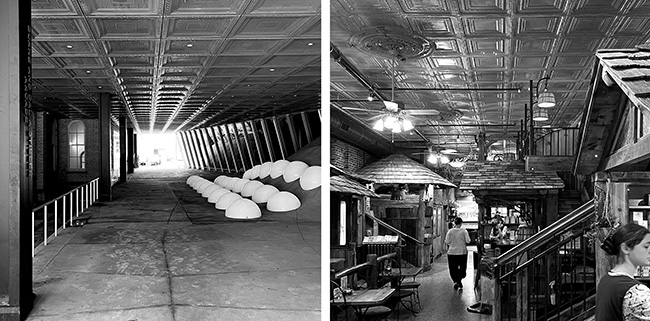
Figure 7.8. The spaces beneath Milstein Hall's faux-Victorian soffits, in particular the arcade (left), remain largely empty and dysfunctional; the ceiling tile design is modeled after a type of pressed tin ceiling, shown here in Ithaca's historic "Andrus Printing / Home Dairy / Firebrand Books Building" (right), that was invented in the U.S. in the late nineteenth century.
Such an expressive gesture may well have been deemed necessary, given the enormous extent of exposed surface area that needed to be covered with something. My criticism isn't that these panels are out of place within "the permanent warfare between the box and the blob" that constitutes the building's primary expressive conceit.23 In fact, the aluminum panels' Postmodern irony (warning: this sentence betrays the author's subjective taste and really has no place in an objective critique) is a welcome relief from the building's other ponderous pretensions. It also helps that these panels are probably the most successfully implemented material detail in the entire building: they have been designed, manufactured, and constructed with thoroughness and precision. The problem is that they can't possibly compensate for the unsustainable design decision that made them necessary in the first place—to lift the entire second floor off the ground, thereby exposing an enormous amount of second-floor surface area to heat loss and heat gain, both directly through the floor as well as through the steel columns that necessarily penetrate the floor insulation as thermal bridges.
- From Cornell's website: "The roof of Milstein Hall is considered another facade of the building, reinforcing the concept of the building as a connector. The entire roof, with the exception of the skylights, is vegetated in a graphic pattern of two types of sedum plantings."24
Characterizing the roof of Milstein Hall as a "facade" is problematic for a number of reasons, some of which have been discussed previously. First, the roof is barely visible, and—when it is seen at all—it is seen obliquely, e.g., from the third-floor studios in Sibley Hall, rather than frontally. On this basis alone, the term "facade" seems inappropriate. Second, the "graphic pattern" painstakingly created with circles of colored sedums has been virtually obliterated, both by natural processes and by maintenance (fig. 7.9).
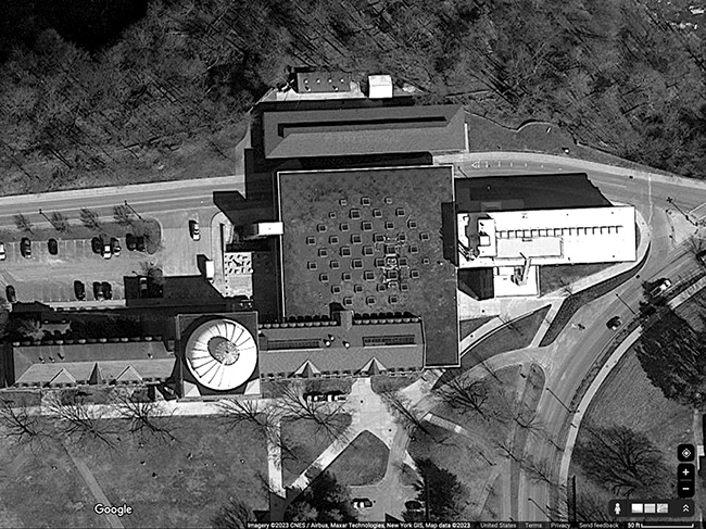
Figure 7.9. This Google Map satellite image shows how the "graphic pattern" of circles created by colored sedums on the vegetated roof of Milstein Hall has been virtually obliterated, both by natural processes and by maintenance; see also figure 6.6.
Third, the flatness of the roof may have been partly responsible for the ongoing problem of leaks that has plagued the building since it first opened, discussed in chapter 10.
- From Cornell's website: "Covered outdoor areas give architects, artists, and fabricators virtually boundless studio space, where they can construct large-scale prototypes, models, and sculptures."25
There are five "covered outdoor areas" in Milstein Hall, and none of them provide "boundless studio space" for the construction of anything, although many of them are used inappropriately for spray painting models and off-loading cigarette butts and other detritus. The dark, dismal, and almost-always-empty arcade (see fig. 6.8 or fig. 7.8 left) has already been discussed; it certainly does not provide any useful studio space for the college.
The four other covered spaces have even less chance of being used than the arcade. Three of these spaces, like the arcade, are covered by the stamped aluminum soffit under the second-floor studio. The first of these spaces consists of a flat concrete surface off University Avenue, across from the Foundry, that morphs into the Crit Room's domed ceiling where it supports some circular bike racks, but certainly no "boundless studio space." Students do use the space occasionally and inappropriately, for spray painting models and for whatever else may have caused those white Giacometti-like residues (fig. 7.10).
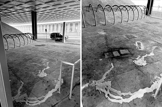
Figure 7.10. These Milstein Hall images of the covered outdoor space across from the Foundry were taken about a month apart in April (left) and May (right) 2023; one can see the addition of spray paint to the illicit composition that was already in place on the concrete surface: a work in progress!
The second of these covered spaces is the largest of them all, and the most useless: this is the portion of University Avenue that runs below Milstein Hall's cantilevered second-floor studios (fig. 7.11). Clearly, it does not, and cannot, function as anything other than a road and sidewalk— certainly not as "boundless studio space [for the construction of] large-scale prototypes, models, and sculptures."
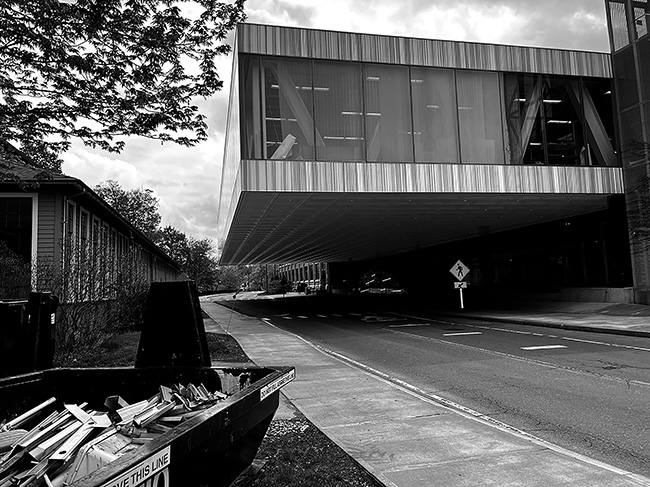
Figure 7.11. The outdoor covered space below Milstein Hall's primary cantilever functions as a road and sidewalk—nothing else.
The third covered space is under Milstein Hall's cantilevered projection to the south, hugging the east wall of Sibley Hall. This cantilever awkwardly protrudes over the main circulation path from the North Campus residential dorms to the Arts Quad and the space below consists of nothing other than circulation paths leading to the arcade and to University Avenue (fig. 7.12). There is certainly no evidence here of "boundless studio space."
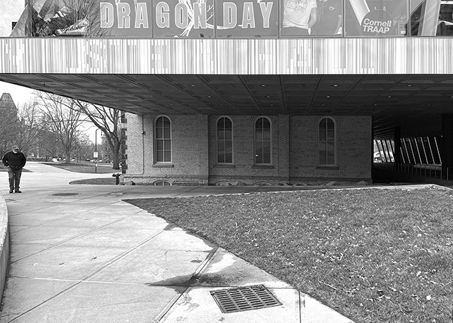
Figure 7.12. The south cantilever of Milstein Hall protrudes awkwardly over the main circulation path from North Campus to the Arts Quad; the space below consists of circulation paths to the arcade and to University Avenue.
There is, however, an air intake grille adjacent to the circulation path (fig. 7.13), which provides an opportunity for students to spray paint their models while simultaneously poisoning the air supply for Milstein Hall's auditorium, Crit Room, and other below-ground spaces.
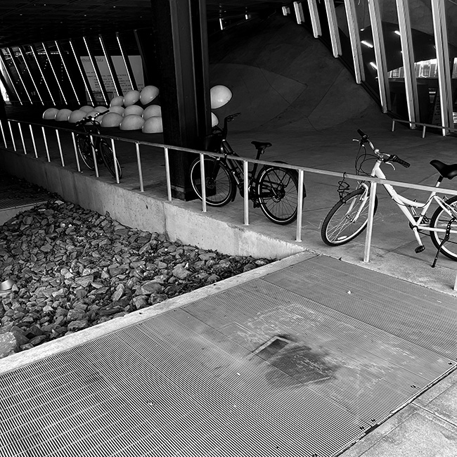
Figure 7.13. An air supply grille for Milstein Hall's basement mechanical room provides an opportunity for students to spray paint their models while simultaneously poisoning the air supply for the auditorium and Crit Room.
The final covered outdoor space, and the only one not under Milstein Hall's pressed aluminum soffit panels, is the exterior exit stairway on the west side of the building. Clearly, the open spaces in this stairway should not be used for anything other than entering or exiting the building, and the building code prevents "the open space under exterior stairways [from being used] for any purpose."26 This doesn't prevent the stairway from being appropriated as a de facto spray paint booth, solid waste disposal site, and smoking room (fig. 7.14).
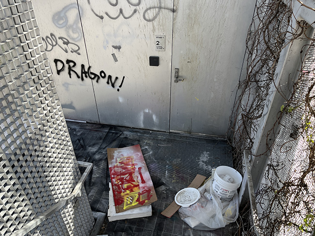
Figure 7.14. The exterior stairway on the west side of Milstein Hall has been appropriated as a de facto spray paint booth, solid waste disposal site, and smoking room, but certainly cannot function as "boundless studio space."
So the last opportunity to find useful outdoor covered areas has fallen short. The claim that Milstein Hall's covered outdoor areas provide "architects, artists, and fabricators virtually boundless studio space, where they can construct large-scale prototypes, models, and sculptures" turns out to be nothing but a transparent and egregious fiction.
Notes
1 " 'In Defense of Food' Author Offers Advice For Health," NPR, Jan 1, 2008, accessed May 2, 2023, here.
2 Lstiburek, "BSI-018: Westford House," 5.
3 "The pattern language we have given here contains 253 patterns. You can therefore use it to generate an almost unimaginably large number of possible different smaller languages…" Alexander, Pattern Language, xxxviii.
4 Jonathan Ochshorn, "Introducing: Building Bad by Jonathan Ochshorn," Lund Humphries (blog), Jan. 8, 2021, accessed April 20, 2023, here.
5 For a discussion of the dysfunctional competition that drives defamiliarized avant-garde design, see Ochshorn, Building Bad.
6 "Milstein Hall Cornell University."
7 Veblen, Theory of the Leisure Class, 176–77.
8 Koolhaas, Delirious New York. See "fictional conclusion," 293 and "theoretical Manhattan," 11 (italics in the original).
9 Koolhaas, Delirious New York, 241.
10 "Milstein Hall Cornell University."
11 "Milstein Hall's Innovative Design."
12 Lechner, Heating, Cooling, Lighting, 130.
13 I made the following rough calculations for the volume and exposed surface area of Milstein Hall (using Imperial units). The volume was calculated by multiplying the various floor areas by their floor-to-floor heights:
Second floor = 25,919 square feet × 15.5 ft = 401,745 cubic feet
First floor = 6,470 square feet × 15.6 ft = 100,932 cubic feet
Basement = 19,568 square feet × 11.3 ft = 221,118 cubic feet
Total volume: 723,795 cubic feet
The exposed surface area (roofs, exterior soffits, and exterior walls) are as follows:
Second-floor roof = 25,919 square feet
Exterior soffit = 19,449 square feet
Basement roof = 13,098 square feet
Second floor glazed walls = 7,642 square feet
First floor glazed walls = 6,724 square feet
Basement garden walls = 1,153 square feet
Total exposed surface area = 73,984 square feet
To compute the surface area of a more rationally configured building with a width of 64 feet, I assumed a total building height equal to that of Milstein Hall (15.5 + 15.6 + 11.3 feet) plus an additional story of 15.5 feet for a total height, including the basement, of 57.9 feet. Dividing the building volume of 723,795 cubic feet by this height of 57.9 feet, we get a per-floor area of 12,500 square feet. The plan dimensions (with a 64-foot width) are therefore 195 feet × 64 feet. The exposed surface area consists of a roof of 12,500 square feet plus a total wall area equal to the building height above grade times the building perimeter, or 46.6 feet × 518 feet = 24,139 square feet, for a total exposed surface area, including the roof, of 36,639 square feet.
14 "Milstein Hall Cornell University" (my italics).
15 Murphy, "Milstein Hall by OMA."
16 I used a simplified structural model created with STRIAN (here). The same steel wide-flange cross-sections and plate girders specified in the structural working drawings for Milstein Hall's "Truss 3" were used, both for the existing hybrid condition and for my modified version. Centerline dimensions were rounded to the nearest foot, and the truss's three rigidly connected columns were replaced with a pin (hinge) and two rollers at the equivalent locations under the bottom chord. Importantly, I have computed moments, shears, axial forces, and deflections based only on a uniformly distributed load of 5 kips/foot (73 kn/m) placed on the top and bottom chords, and have not computed the maximum moments and internal forces based on the consideration of all relevant load scenarios. The distributed load of 5 kips/foot (73 kn/m) is equivalent to floor and roof loads of about 150 psf (7.2 kPa), somewhat lower than the distributed live and dead loads specified for this building. The point was not to replicate the forces, moments, and deflections computed by the structural engineers, but rather to show that the decision to misalign vertical and diagonal members in the hybrid truss greatly increases the magnitude of bending moments in particular.
17 "Milstein Hall's Innovative Design."
18 Ochshorn, Building Bad, 146.
19 Ochshorn, "Revisiting Form and Forces," 75.
20 Ochshorn, "Revisiting Form and Forces," 75.
21 Shohei Shigematsu is quoted in Murphy, "Milstein Hall by OMA."
22 "The Unassuming History of Tin Ceilings," American Tin Ceilings, accessed April 21, 2023, here.
23 Shohei Shigematsu is quoted in Pearson, "Milstein Hall."
24 "Milstein Hall's Innovative Design."
25 "Milstein Hall's Innovative Design."
26 "1011.7.4 Enclosures under exterior stairways," ICC, Building Code of New York State, 2020 (my italics).
contact | contents | bibliography | illustration credits | ⇦ chapter 6 |